WWW.NNC.IR
Checking the System Configuration
38
Vision System FH/FZ5 Series
User’s Manual (Z340)
Checking the System Configuration
System Configuration
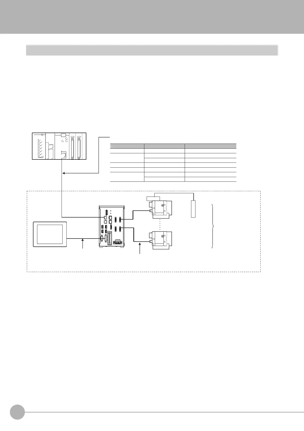
The FH/FZ5 is a Vision Sensor that uses a controller to process measurements of objects that are imaged with a
Camera.
You connect an LCD for operations and monitoring, and various Cameras to the FH/FZ5-series Sensor
Controller.
You connect external devices, such as a PLC or a computer, through a parallel, Ethernet, or RS-232C cable.
You can connect up to eight Cameras, depending on the model of the Controller.
To measure more than one line with a single Sensor Controller, you assign the Camera for the measurements to
each line beforehand, and switch between Cameras during the measurement flow.
Communications protocol
Communications cable Connector on the FH
Parallel Parallel I/O cable I/O connector
Ethernet cable Ethernet connectorPLC Link
RS-232C cable RS-232C connector
EtherNet/IP Ethernet cable Ethernet connector
EtherCAT Ethernet cable
Connector for EtherCAT communications
Ethernet cable Ethernet connectorNon-procedure
RS-232C cable RS-232C connector
FH/FZ5
LCD
FZ-M08
(8.4-inch)
Camera
Camera
Sensor Controller
• Controller with 2 Camera channels
• Controller with 4 Camera channels
• Controller with 8 Camera channels
Camera Cable (e.g., FZ-VS)
Communications cable
External device (e.g., PLC)
*1. FZ-MEM2G or FZ-MEM8G USB Memory is sold separately.
Lighting
FZ-VM Monitor Cable +
FH-VMRGB DVI Adapter
(DVI Adapter: FH-series
Vision Sensor only)
Up to 2, 4, or 8 Cameras
depending on the model of
the FH/FZ5-series Sensor
Controller

 Loading...

