WWW.NNC.IR
Setting the Camera Conditions
265
7
Changing the System Environment
Vision System FH/FZ5 Series
User’s Manual (Z340)
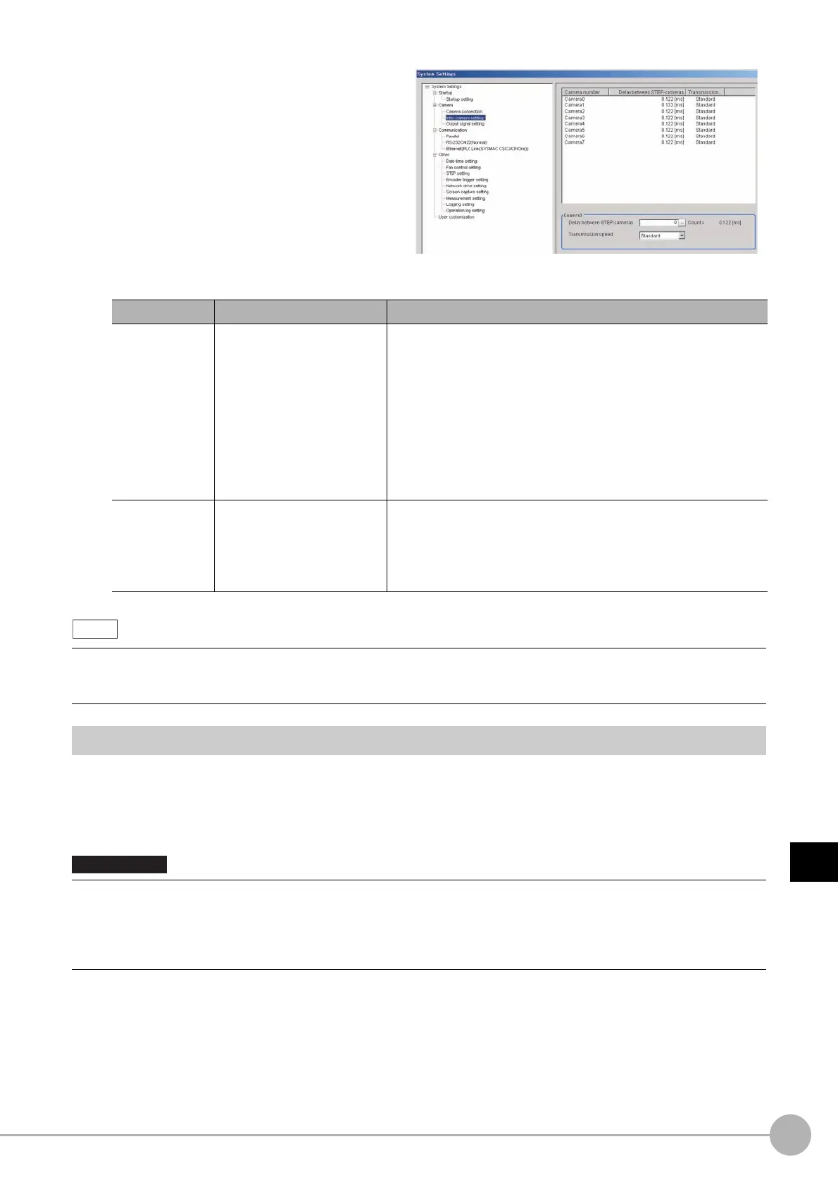
1 In the Main Window, select [System
settings] − [Camera] − [Inter-camera
setting] from the [Tool] menu
The Inter-camera Settings View is displayed.
2 Click a camera number to set the delay
between STEP-cameras and then specify
the delay count value.
Setting the SHTOUT Signal: [Output Signal Settings]
This function is exclusively for an FH Sensor Controller.
This setting affects the SHTOUT signal that is output when the exposure of the Camera ends.You can detect
when the exposure ends with the SHTOUT signal to minimize the time to hold the workpieces still for taking
images. This allows you to move the workpiece or the Camera immediately after the exposure ends.
Item Set value [Factory default] Description
Delay count
between STEP-
cameras
[0] to 511
(1 count is 30 μs)
Sets the delay time from when the STEP signal is received to when
exposure begins for the selected Camera.
The delay count - delay time conversion equation for the FH sensor
controller and that for the FZ5 sensor controller differ.
The delay time for the FZ5 equivalents to the displayed time value
in the Delay between STEP-cameras field (= Delay count between
STEP-cameras x 30 μs + 122 μs).
The delay time for the FH equivalents to the displayed time value in
the Delay between STEP-cameras field (= Delay count between
STEP-cameras x 30 μs + 122 μs) + 120 μs.
Transmission
speed
[Standard] or High speed
If you use a Camera Cable that is shorter than 5 m to connect to an
FH-SC/SM Camera, you can use the [High speed mode]
option to reduce the image input time.
Refer to the instruction manual for the Camera for actual frame
rates.
With an FH Sensor Controller, you can make Camera settings for up to eight Cameras.
With an FZ5 Sensor Controller, you can make Camera settings for up to four Cameras, Camera 0 to Camera 3. If you make
changes to the setting for Camera 4 to Camera 7, they will not be applied.
• You cannot use the STGOUT signal and SHTOUT signal at the same time. Select the signal to output depending on the
application.
• The settings of the [Output Signal Settings] apply only to the FH.
With an FZ5 Sensor Controller, you cannot use the SHTOUT signal even if you change the settings of the [Output Signal
Settings].

 Loading...

