PG-FP6 V1.06 10. Connectors and Cables
R20UT4469EJ0800 Rev.8.00 Page 138 of 188
Oct.01.21
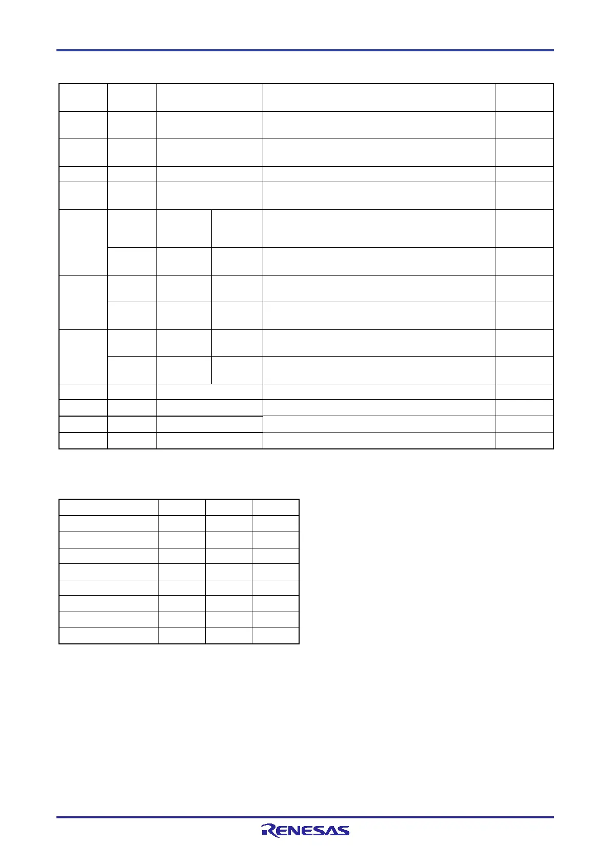
Table 10.5 Pin Functions of the Remote Interface
Number
Output
Level
Indicates that the remote interface is connected. When
the power of the FP6 is ON, the CONN is always valid.
2 Output BUSY Outputs the status indicated by the status LED
“BUSY”.
High level
Outputs the status indicated by the status LED “PASS”.
4 Output ERROR Outputs the status indicated by the status LED
“ERROR”.
High level
other than
bank mode
Same as the function of the CANCEL button.
Input Bank mode BANK0 Indicates the lowest 1 bit of the 3-bit programming area
number.
Low level
mode
Same as the function of the ENTER button.
Input Bank mode BANK1 Indicates the middle 1 bit of the 3-bit programming
area number.
Low level
mode
Same as the function of the NEXT button.
Input Bank mode BANK2 Indicates the highest 1 bit of the 3-bit programming
area number.
Low level
Inputs the “START” (Start command) signal.
Clears the “PASS” and “ERROR” signals.
Note: Each input pin is pulled-up inside the FP6.
Table 10.6 Programming Areas and Banks
Programming area 1 0 0 1
Programming area 3 0 1 1
Programming area 5 1 0 1
Programming area 7 1 1 1
Remark: 0: Low level
1: High level
Note: Set BANK0, BANK1, and BANK2 to the low level in programming area 0. Set BANK0 and BANK1 to the high
level and BANK2 to the low level in programming area 3.

 Loading...


