PG-FP6 V1.06 2. FP6 Main Unit: Names and Functions of Parts
R20UT4469EJ0800 Rev.8.00 Page 26 of 188
Oct.01.21
2.FP6 Main Unit: Names and Functions of Parts
This chapter gives the names and functions of the parts on the FP6 main unit.
2.1 FP6 Control Panel
Indicators and buttons are placed on the top of the FP6.
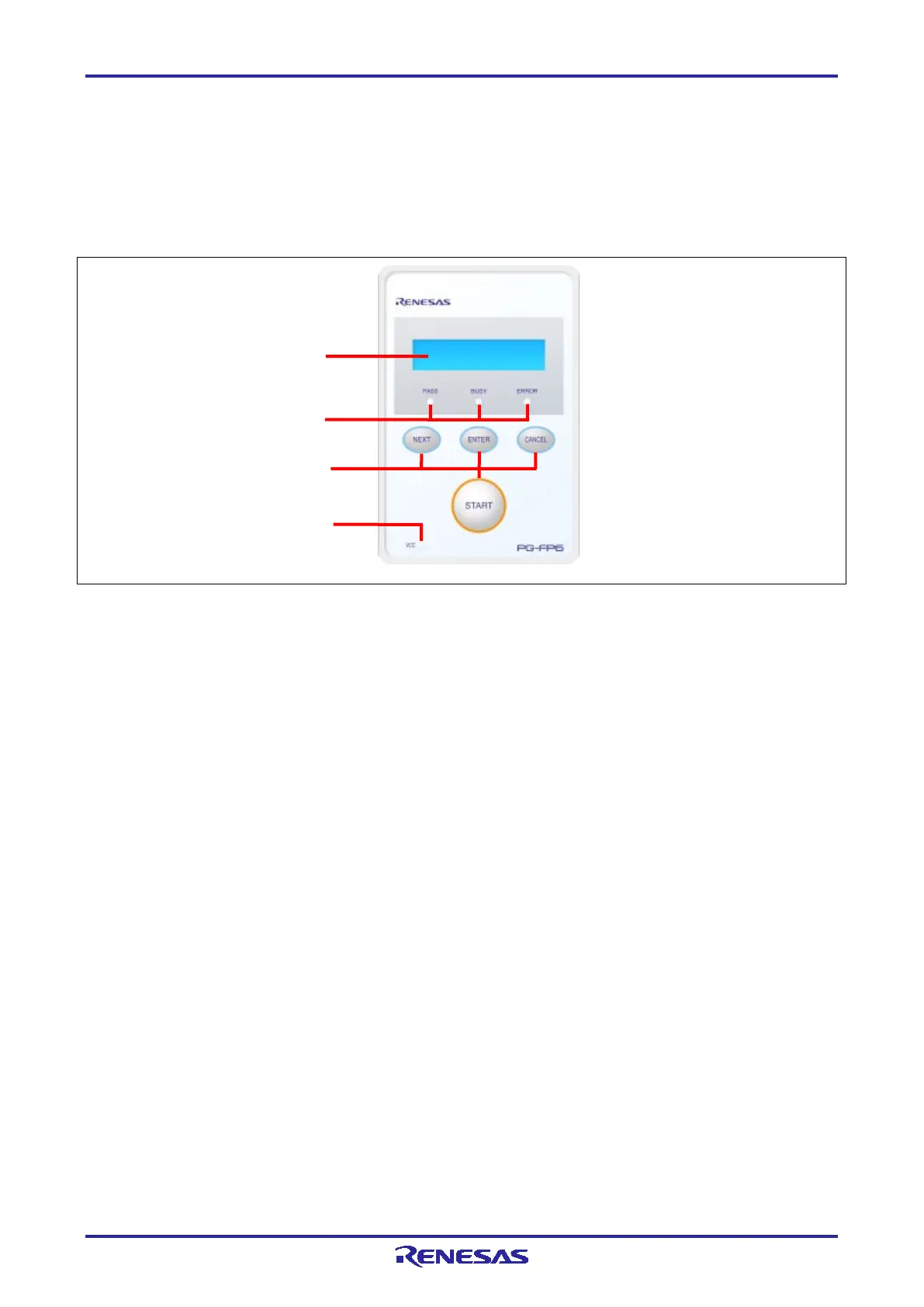
Figure 2.1 FP6 Top View <Control Panel>
(1) Indicators
•
An LCD display of 16 × 2 characters that indicates the operating mode or
menus.
It is mainly used when the FP6 is in standalone mode.
•
These LEDs show the operating state of the FP6.
PASS (blue) indicates a normal end, BUSY (orange) indicates processing in
progress, and ERROR (red) indicates an abnormal end.
•
This LED is illuminated (green) when power is being supplied to the user
system.
(2) Buttons
•
Proceeds to the next menu item.
•
Selects the item shown in the message display.
•
Cancels the current selection and returns to the previous menu item. The
currently running command cannot be stopped, except for the [Read] command.
•
Executes the [Start] command with the current active-programming-area setting.

 Loading...


