PG-FP6 V1.06 11. Examples of Connections with Microcontrollers
R20UT4469EJ0800 Rev.8.00 Page 146 of 188
Oct.01.21
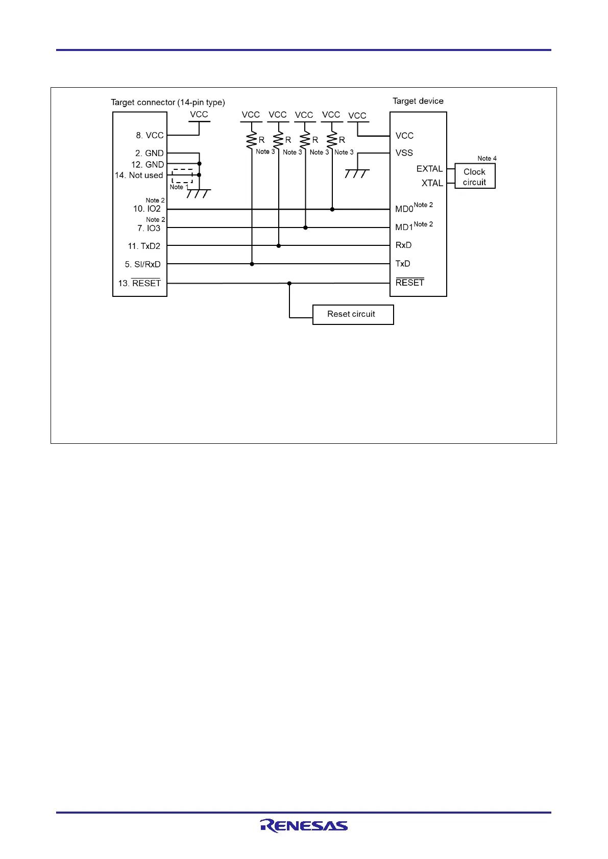
11.11 RX and SuperH (SCI communications)
Notes: 1. These pins do not need to be short-circuited unless the FP6 is used with the E1, E20, E2, E2 Lite, or E8a.
2. Connect the mode setting pins of operating mode to any of the IO0 to IO5 pins. The signal settings for IO0 to
IO5 pins can be set in the [Mode Pins Setting] dialog box on the [Connect Setting] tab in the [Setup] dialog
box. Normally, use the initial settings in the [IO Signal Settings] area. It is compatible with examples of circuits
in the E1/E20 Emulator Additional Document for User's Manual (RX User System Design).
3. The value of each resistor should be in the range from 4.7 KΩ to 10 KΩ.
4. The need for the clock circuit might differ depending on the target device. Refer to the user’s manual of the
target device.
Figure 11.11 Example of a Circuit for RX Family and SuperH Family (SCI) (Case of RX62T)

 Loading...


