PG-FP6 V1.06 11. Examples of Connections with Microcontrollers
R20UT4469EJ0800 Rev.8.00 Page 151 of 188
Oct.01.21
11.18 RE (UART communications)
The following shows the conversion of each signal when a 14-pin target cable and 20-pin conversion adapter
are connected to the 15-pin D-sub connector of the PG-FP6.
Table 11.1 List of Signal Connections for RE Family
Signal Name
(PG-FP6)
15-Pin D-Sub Male
Connector
14-Pin 2.54-mm Pitch
Multipurpose Female
Connector
CoreSight 20-pin
Female Connector
RE Signal Name
GND 15 2, 12 3, 5, 15, 17, 19 VSS
TxD2/HS 7 11 8* MD
FLMD1 6 9 2 RxD
Note: Switching pin 8 between use as the MD pin and as the TDI pin during debugging requires a switching circuit.
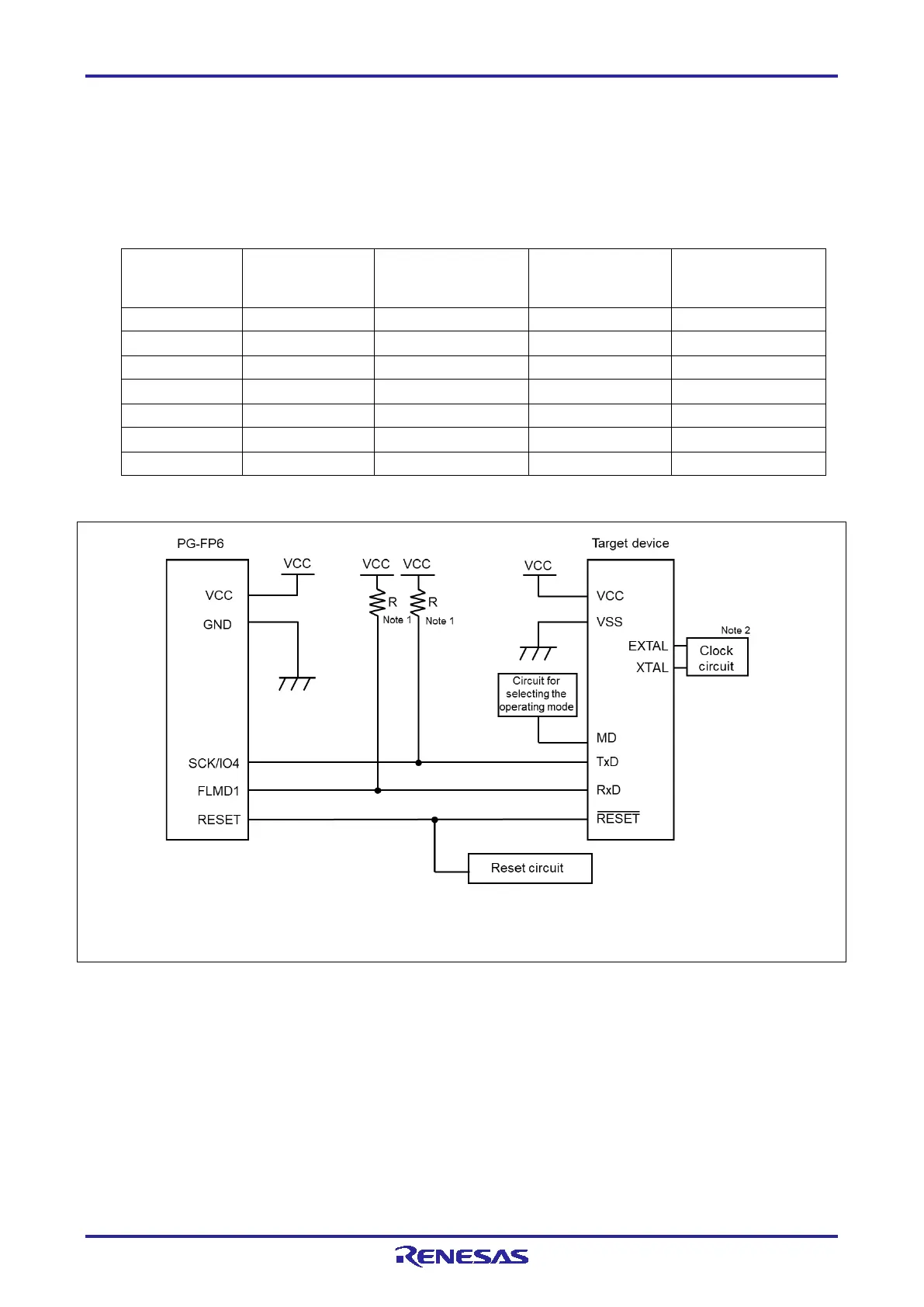
Notes: 1. The value of each resistor should be in the range from 4.7 KΩ to 10 KΩ.
2. Some target devices do not require an external clock circuit. To check if the clock circuit is necessary, see the
user’s manual of the target device.
Figure 11.18 Example of a Circuit for R7F0E017D (UART communications)

 Loading...


