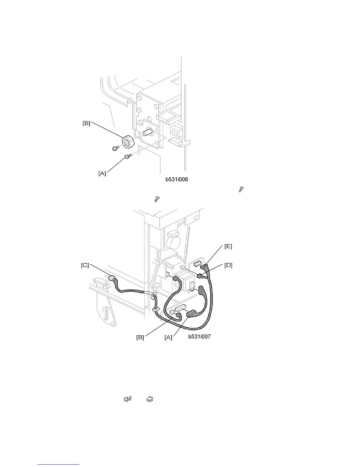
Punch Unit (B531)
D062/D063/D065/D066 2-52 SM
12. At the front, secure the punch unit [A] with the large step screw ( x 1, M4 x 10).
13. Attach the punch unit knob [B] (
x 1).
14. Connect the PCB harness connector [A] to CN129 of the finisher PCB and to CN600 of
the punch unit PCB.
15. Connect the HP Sensor 2 harness connector [B] to CN130 of the finisher PCB and to
HP Sensor 2.
16. Connect the single end of the hopper full sensor connector cable [C] to the hopper full
sensor on the arm (
x 1, x 1), then connect the other two connectors to HP
Sensor 1 [D] and CN620 [E] of the punch PCB.