Section 05 ELECTRICA L SYSTEM
Subsection 06 (INFORMATION CENTER)
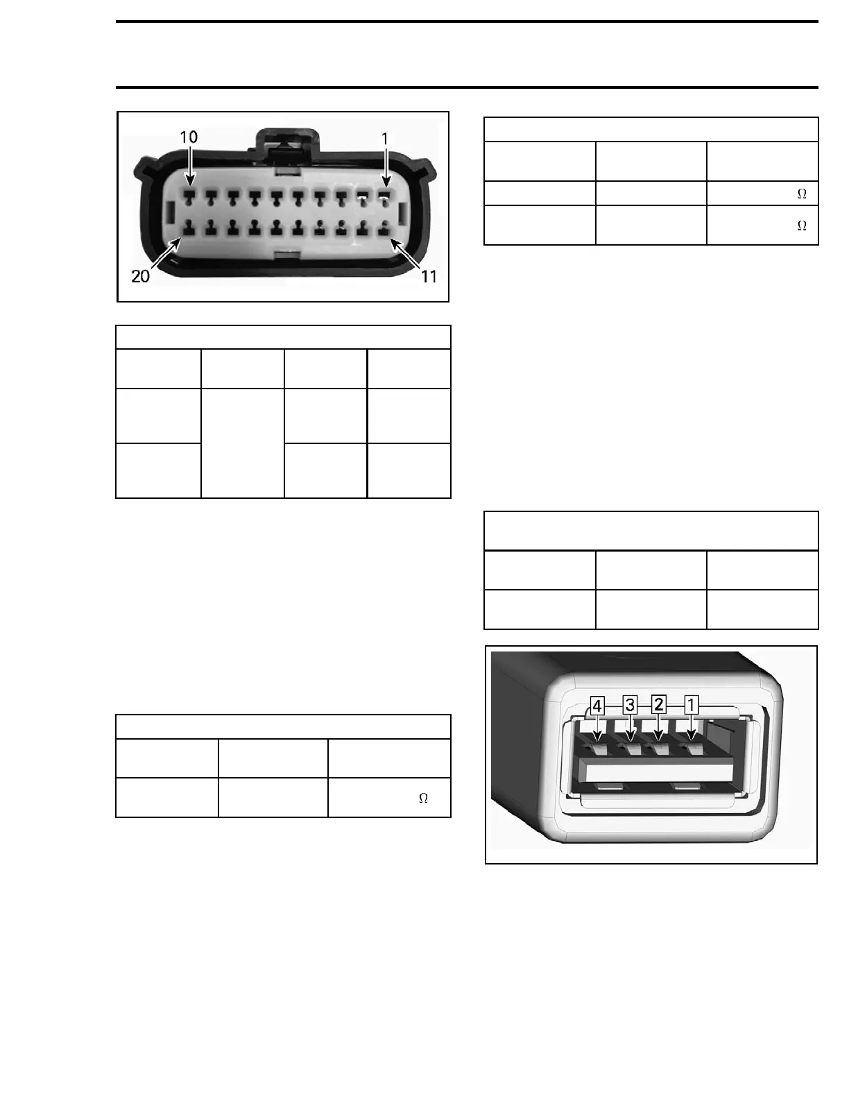
219100949-018-001_a
MULTIFUNCTION GAUGE CONNECTOR (PIN-OUT)
MULTIFUNCTION GAUGE POWER TEST
CL_A
CONNECTOR
BATTERY
IGNITION
POSITION
SPECIFI
CATION
pin 1 Any
Close to
battery
voltage
pin 11
Negative
(-) post
ON
Close to
battery
voltage
If there is no power at pin 1, check fuse F10 and
the related circuit.
If there is no power at pin 11, in check fuse F7,
MAIN relay RY1, and the related circuit.
If the power test is within specification, continue
with
TESTING THE MULTIFUNCTION GAUGE
GROUND CIRCUIT
.
Testing the Multifunction Gauge
Ground Circuit
Test as per the following table.
MULTIFUNCTION GAUGE GROUND TEST
CL_A
CONNECTOR
BATTERY SPECIFICATION
Pin 2
Negative (-)
post
Close to
1
If the ground at pin 2 is not within specification,
check the related circuit.
If the ground tested to specification, continue
with
TESTING THE MULTIFUNCTION GAUGE
CAN CIRCUIT
.
Testing the Multifunction Gauge CAN
Circuit
1. Remove the seats for access to the DLC (Diag-
nostic Link Connector). Refer to
BODY
subsec-
tion.
2. Test as per the following table.
MULTIFUNCTION
GAUGE CAN WIRE TEST
CL_A
CONNECTOR
DLC SPECIFICATION
Pin13(CANHI)
Pin 1
Close to 0.4
Pin14(CAN
LO)
Pin 2
Close to 0.4
If the CAN wire verification test fails, check the
related circuit.
If the m ultifunction gauge functions, however
there is a suspected communication problem with
another component, perform this test between
the multifunction gauge and that component.
If the multifunction gauge power, ground and
CAN verification tests are all to specifications and
the multifunction gauge is inoperative, replace
the multifunction gauge.
Testing the Multifunction Gauge USB
Power Voltage
1. Test as per the following table.
MULTIFUNCTION GAUGE USB POWER
VOLTAGE TEST AT USB CONNECTOR
USB
CONNECTOR
BATTERY SPECIFICATION
Pin 1
Negative (-)
post
Closeto5V
219100949-018-004_a
USB CONNECTOR PINOUT
1. Pin 1 (5V)
2. Pin 2 (Data -)
3. Pin 3 (Data +)
4. Pin 4 (Ground)
If result is not as per specification, continue with
the following steps.
2. Disconnect c onnector CL_B from the gauge.
3. Test as per the following table.
219101047-001 141

 Loading...


