Digital Electronic Modules
11-42
ET 200S Distributed I/O System
EWA-4NEB 780602402-12
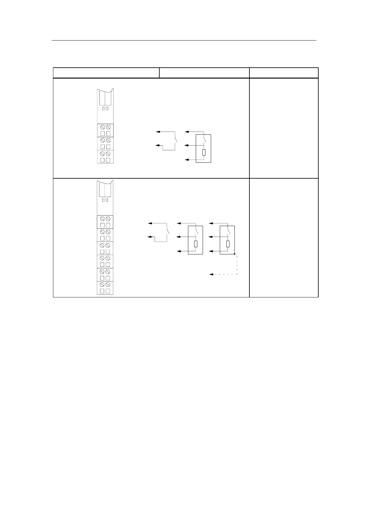
Table 11-17 Terminal assignment of the 2DI 24 VDC Standard, continued
View RemarksTerminal assignment
NN
L1L1
2
3
6
7
15
DI
1
DI
0
2-wire 3-wire
TM-E15S23-01 and 2DI 120 VAC Standard
CH1CH0
Channel 0: Terminals 1 to
3
Channel 1: Terminals 5 to
7
DI: Input signal
L1: Sensor supply
N: Neutral wire
NN
L1L1
2
3
4
6
7
8
1
5
DI
1
DI
0
2-wire 3-wire
TM-E15S26-A1 and 2DI 120 VAC Standard
CH1CH0
AUX1
A
4
A
3
A
8
A
7
AUX1
AUX1
AUX1
n. c.n. c.
4-wire
AUX1 must be occupied with
4 wires at PE
Channel 0: Terminals 1 to
A3
Channel 1: Terminals 5 to
A7
DI: Input signal
L1: Sensor supply
N: Neutral wire
Terminals 4 and 8 can be
used for connection of
cables that are not
required up to 120 VAC.

 Loading...


