Analog Electronic Modules
12-26
ET 200S Distributed I/O System
EWA-4NEB 780602402-12
12.2.3 Instructions and circuits for unused channels of the
analog input modules
• ”Disable” unused input channels in the configuration.
• A disabled channel always return the value 7FFF
H
.
• The cycle time of the modules is halved with the standard modules 2AI U, 2AI I
2WIRE, 2AI I 4WIRE, 2AI RTD Standard, 2AI RTD High Feature and 2AI TC
Standard, 2AI TC High Feature.
• The cycle time remains unchanged with the 4AI I 2WIRE standard module.
• The cycle time remains unchanged at 1 ms with the 2AI U, 2AI I 2WIRE and
2AI I 4WIRE high-speed modules.
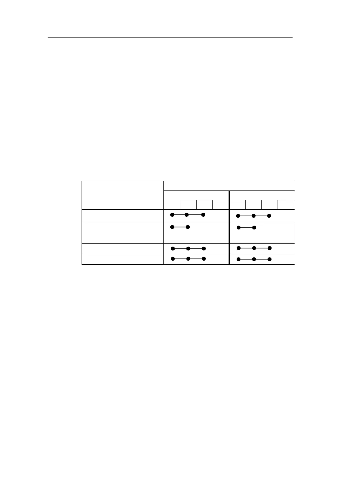
• To maintain the approved potential differences (U
CM
) bridges must be wired to
the terminal module on the unused channels. This is required for the following
modules:
Analog input module
TM connection terminal
Channel 0 Channel 1
1 2 3 4 5 6 7 8
2AI U Standard
2AI RTD Standard, 2AI RTD High
Feature,
2AI TC High Feature
2AI TC Standard
2AI U High Speed
12.3 Response of the Analog Modules during Operation and if
Faults Occur
This chapter describes:
• The dependence of the analog input and output values on the supply voltage of
the electronic module and the operating states of the PLC.
• The response of the analog electronic modules depending on the state of the
analog values in the specific value range.
• The influence of errors on the analog inputs and outputs.
• Use of the shield.

 Loading...


