97
Section 9 Scope and Multimeter Operations
Introduction
This section describes the basic operation and navigation of the
Scope Multimeter function.
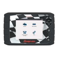
Selecting Scope Multimeter provides access to all the tools needed
for performing electrical circuit tests and monitoring signals. The
Scope Multimeter function works interactively with other functions.
Selecting “View Meter” from a Guided Component Test or Scanner Test opens the
Scope Multimeter function.
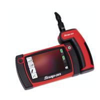
In situations where the testing connection points are not easily accessible, the
Scope Module easily separates from the diagnostic tool (connected via extended
length USB cable) allowing you to monitor the results remotely.
9.1 Main Topics Links
(Select topic to link to section)
• Capturing Data page 126
• Component Locations page 99
• Control Panel and Settings page 114
• Control Panel (Trace Controls Quick Reference) page 115
• Cursors page 125
• Digital Multimeter (DMM) page 101
• Getting Started page 103
• Graphing Multimeter (GMM) page 101
• Ignition Scope page 132
• Lab Scope page 102
• Main Screen and Toolbars page 107
• Pairing and Hardware Status Icons page 105
• Tests and Capabilities (Quick Reference) page 99
• Test Leads and Accessories page 143
• Testing Capabilities page 99
• Triggers page 122
• Trigger Setup Menu page 109
• Safety page 97
• Setup Menu (Preferences) page 108
• Scope/Meter (Upper) Toolbar page 107
• Trigger Operation page 124
• Using the Scope Module Extension Cable page 104
• Reviewing Data and Using Zoom (Review Mode) page 128
9.2 Safety
Risk of electrical shock.
• Read the Safety Information provided for important warnings on the use of
this product
• This product is intended for Measurement Category I (for example,
automotive 12V systems), do not use this product for Measurement
Categories II, III, and IV.
• Measurement Category I is for performing measurements on circuits not
directly connected to MAINS or MAINS circuits (an example of a MAINS
circuit is 120V AC or 240V AC household or industrial electricity), do not
connect this product to MAINS or MAINS circuits.
• Do not apply the Black Ground Lead to test points other than ground/
system return/vehicle chassis.
Electrical shock can cause personal injury, equipment damage, and/or circuit
damage.
Maximum rated transient over voltage impulse is 500 volts, do not
exceed the rated transient over voltage.
WARN ING