Scope and Multimeter Operations Triggers
122
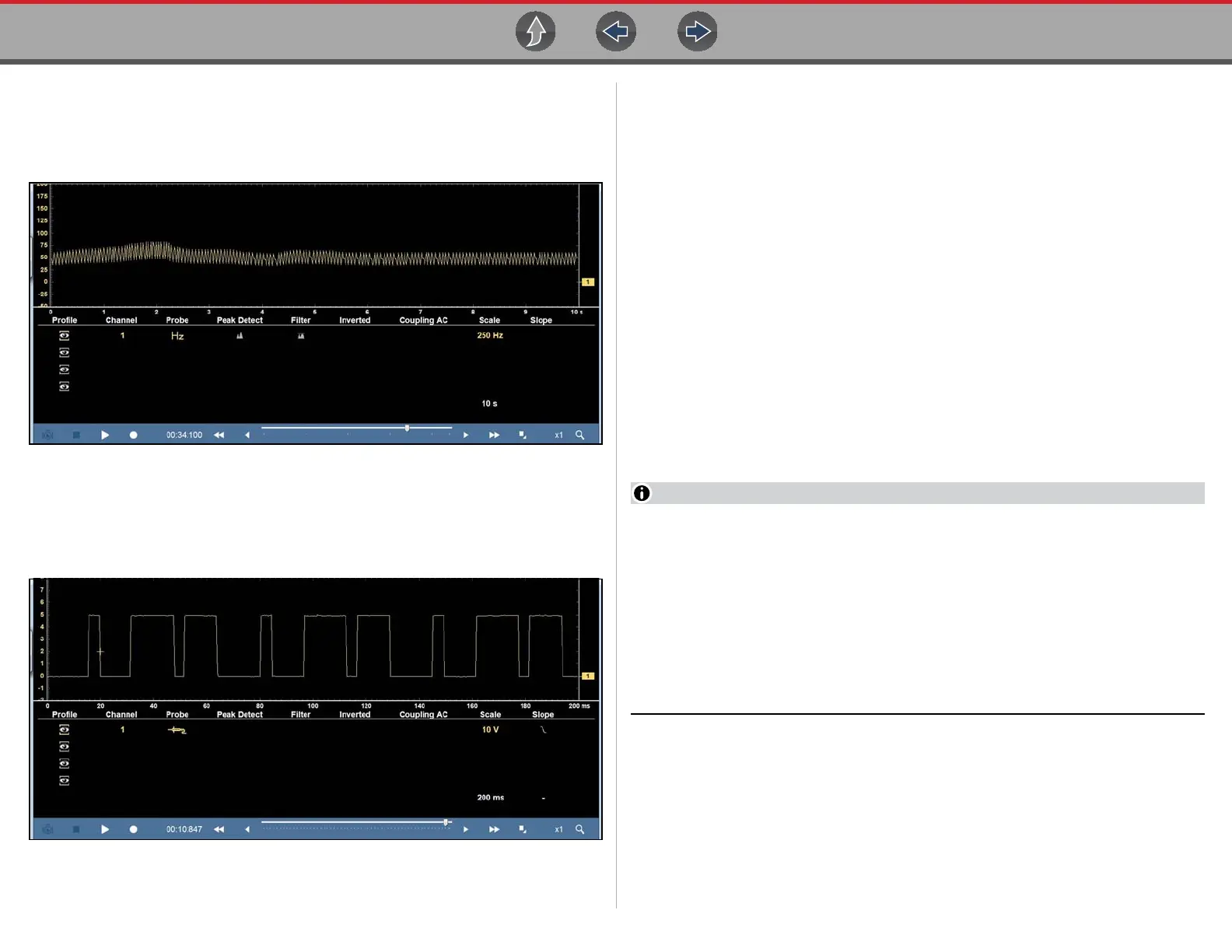
In some instances a signal with unequal spacing may display as a band or ragged
signal, depending on the sweep setup or the measurement type being displayed.
As example, a Cam sensor signal Hz graph (shown in Figure 9-40) may look like
this with a lot of variation.
Figure 9-40 Cam signal (GMM frequency)
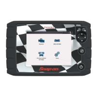
In this situation, you can use the lab scope to verify the signal integrity and spacing.
Displayed in Lab scope (Figure 9-41), it can be seen there is actually variation
which the Hz graph is not displaying.
Figure 9-41 Cam signal (Lab Scope)
9.10 Triggers
Triggers are only available in the lab scope function.
A trigger can be used to stabilize a changing or erratic signal (a signal that may
flicker or drift as it refreshes), so that it is easier to view or diagnose. This
stabilization effect is accomplished by basically displaying the same part of the
trace repeatedly from the same starting point, thus the flicker or drift is minimized.
A trigger is basically a “specific point” on the display, at which a trace will start to
display (start the sweep) if it crosses that point.
The trigger feature allows you to set the conditions of that “specific point” also called
a “trigger point”. When the trigger conditions are set, and a trace “meets” those
conditions (crosses the trigger point), the trace will start.
Trigger conditions:
• Vertical scale position (amplitude)
• Sweep position - the horizontal scale position, or position in time
• Slope direction - the direction the trace must be moving (up/rising or positive)
or (down/falling or negative) when crossing the trigger point.
Triggers can be set on any channel, however only one trigger can be activated
(used) at a time.
If a trigger is set outside the range of the scales, a yellow marker (e.g. arrow
with plus symbol) will be displayed indicating the trigger is out of range and a
confirmation screen will display.
When a trigger is set on a channel, and more than one channel is active
(displayed), trigger conditions must be met for that channel in order to display
all the other channels.
The trigger point is indicated by a plus marker (+) on the scope grid. The trigger
marker sign can be dragged across the grid with the stylus to roughly position it.
The trigger setup menu allows you to precisely position the trigger. See Trigger
Operation on page 124.