Scope and Multimeter Operations Setup Menu (Preferences)
108
9.7.2 Main Body of the Screen
The main body of the screen varies depending on what display options have been
selected. Up to four traces, along with digital readouts of current signal values,
signal status and triggering conditions, can be displayed simultaneously on the
main body of the screen. Adjustments to the display are made through the scope
toolbar as explained above.
Each trace is displayed as voltage over time on a standard oscilloscope screen.
Voltage level is recorded on the vertical, or “y-axis” and time is presented on the
horizontal, or “x-axis” of the screen. Values are shown for each graduation on the
scales.
When using transducers, the pressure being sensed by the transducer is converted
into a voltage signal. However, the values are shown as pressure on the display
screen rather than voltage.
9.8 Setup Menu (Preferences)
Selecting Setup (upper toolbar) opens a menu including the
following options:
Traces - see Trace Controls Menu on page 108
Sweep - see Sweep Scale (X-axis) on page 119
Trigger - see Triggers on page 122
View - see View Controls on page 109
Setup - see Setup Controls on page 113
9.8.1 Trace Controls Menu
Trace controls are used to adjust individual characteristics of how the signal is
sampled and displayed for each of the four traces.
z To adjust trace controls using the menu:
1. Select Setup (upper toolbar).
The Scope Multimeter Preferences dialog box opens.
2. Select Traces.
3. Select the trace to be configured from the submenu.
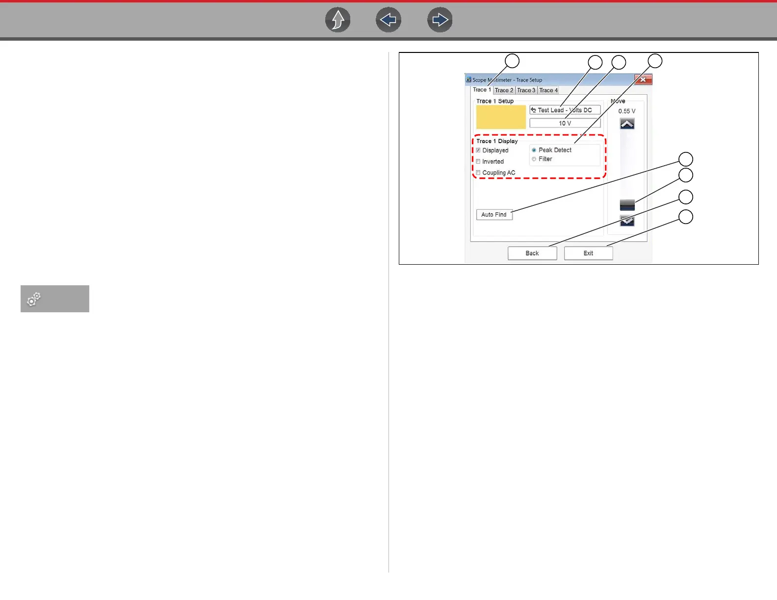
The traces dialog box displays (Figure 9-11).
Figure 9-11 Traces dialog box
1— Trace Setup Tabs - Individual tabs for each trace (channel)
2— Probe Selection Icon - Opens probe selection menu
3— Scale (Vertical) Setting Icon - Opens Scale value selection menu
4— Trace Settings - Select or deselect the trace characteristic items as needed:
– Displayed - display or hide the trace
– Inverted - see Invert Icon on page 118
– Coupling AC - see Coupling AC Icon on page 118
– Peak Detect - see Peak Detect Icon on page 117
– Filter - see Filter Icon on page 118
5— Auto Find - Sets the scope to sample the signal and internally calculate the
best way to display it.
- A scale and the vertical position for the zero line of the trace that allows
the whole waveform to fit on the screen is established when Auto Find is
selected.
- If Auto Find is selected on an armed trigger, it also sets the trigger level
halfway between the minimum and maximum value of the signal to
provide a stable waveform.
6— Zero Baseline Adjustment - use the slider and arrows to precisely adjust
the zero baseline
7— Back - closes the dialog box to return to the Preferences dialog box
8— Exit - closes the dialog box and returns to the scope