Scope and Multimeter Operations Control Panel and Settings
115
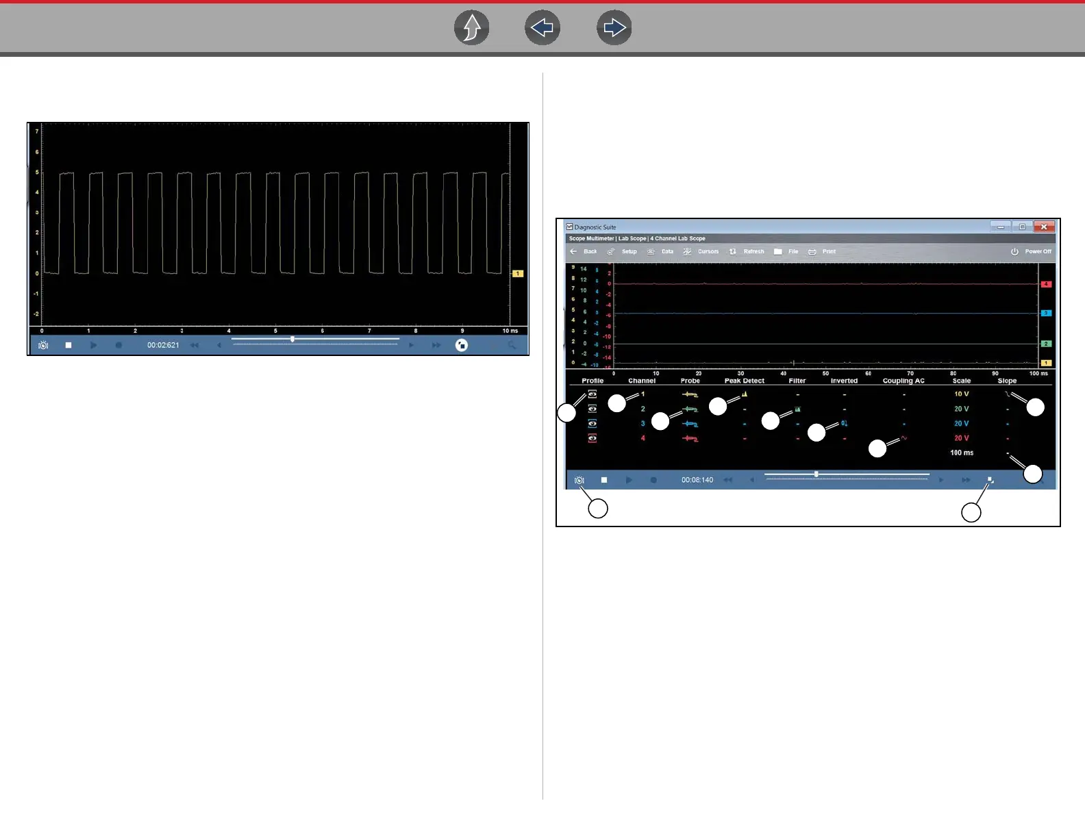
• Control Panel Off— the control panel is not displayed, only the meter screen
is shown (Figure 9-28)
Figure 9-28
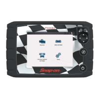
9.9.2 Control Panel (Trace Controls Quick Reference)
Trace (channel) settings and controls can be accessed in the Control Panel and the
Trace Setup menu. Graphic and value icons are used in the control panel to access
the settings. Applicable settings are displayed depending on the test.
Various control icons are shown in the following images, select a callout description
(blue text) to link to that topic.
Figure 9-29
1. Profile Icon
2. Channel Icon
3. Probe Icon
4. Peak Detect Icon
5. Filter Icon
6. Invert Icon
7. Coupling AC Icon
8. Slope (Trigger) Icon
9. Taking a Data Snapshot
10. Expand/Collapse Icon - see
Display Modes
11. Trigger Setup Menu Icon - see
Trigger Setup Menu