Guided Component Tests Tests
95
8.5 Tests
Tests provide specific instructions (if available) to help you perform tests on
components. Selecting a component test opens a preconfigured meter to start the
test, and typically also provides connection instructions, specifications, and testing
tips.
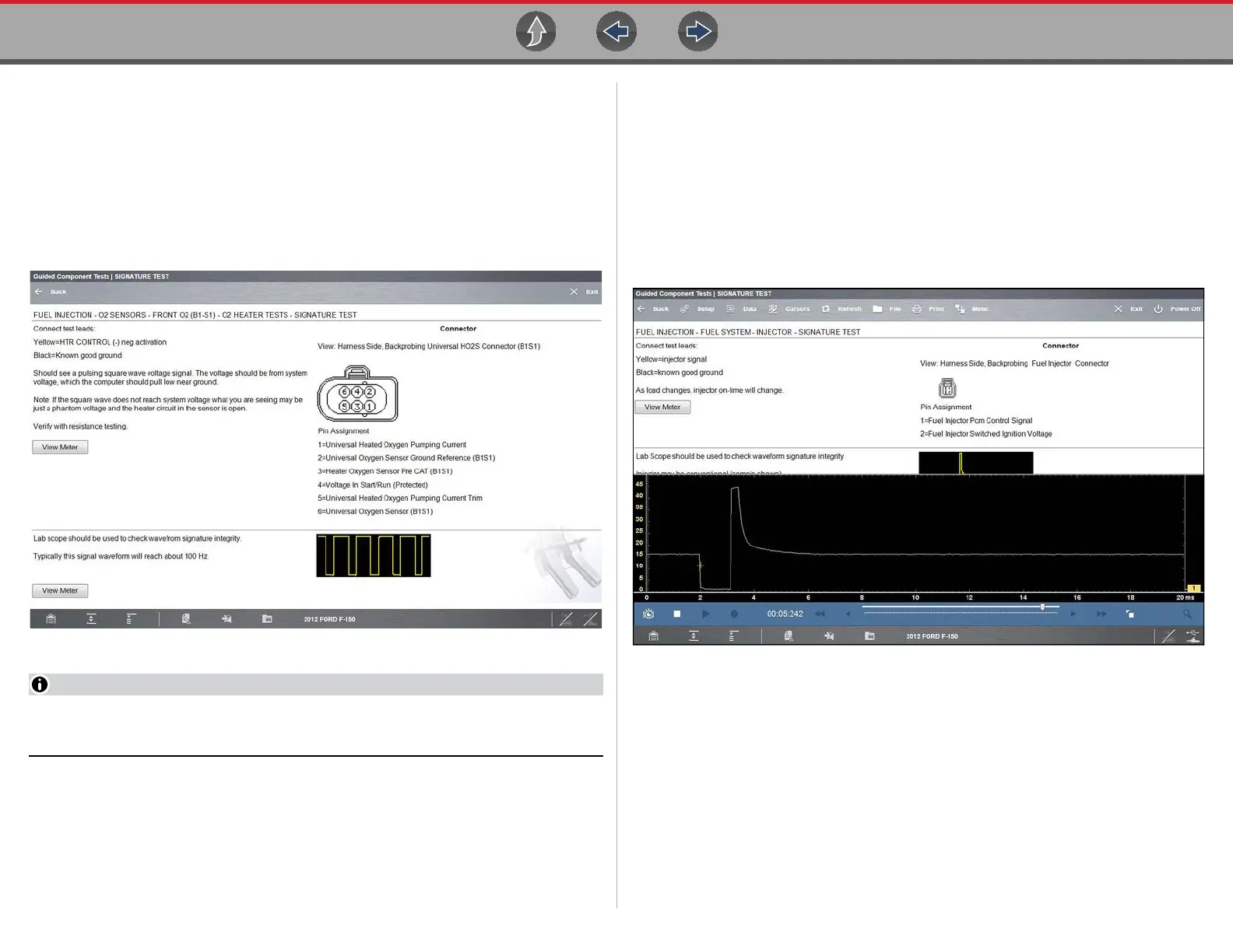
A typical Test screen (Figure 8-6) may contain multiple test options, and information
to assist you perform the test.
Figure 8-6 Typical Signature Test screen
Test screens and menus will vary, and in some instances more than one
selection may be available and/or open a submenu.
Test screens may contain icons and hyperlinks that link to other supporting
information or open test screens. Common links are:
– View Meter—see View Meter on page 95
– Show More Information—opens a new screen with additional information.
8.5.1 View Meter
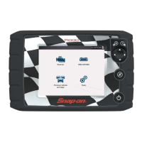
View Meter opens a live meter set up to perform the test in the lower portion of the
screen (Figure 8-7). Once the meter view is open, the Guided Component Test
toolbar at the top of the screen is replaced by the Scope Multimeter toolbar, which
allows you to make adjustments to the settings. See Scope/Meter (Upper) Toolbar
on page 107 for toolbar icon information.
The Meter icon, is only available Guided Component Test view meter mode
(Figure 8-7).
Figure 8-7 Sample view meter window
Three view meter options are available:
1. With View Meter active (Figure 8-7), select the Meter icon on the toolbar once
and the meter expands to fill the entire screen.
2. Select the Meter icon a second time and the meter will open as a separate
window (Figure 8-8). This window can remain open if you switch to the Scan
Module and can be accessed from the Windows toolbar at the bottom of the
screen. You can also resize and reposition the meter window on the screen.