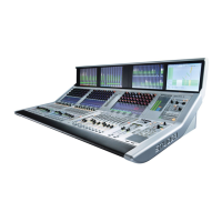
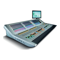
Vista 5 M3 Digital Mixing System
1-10 Introduction
Document generated: 28.08.13
SW V4.9
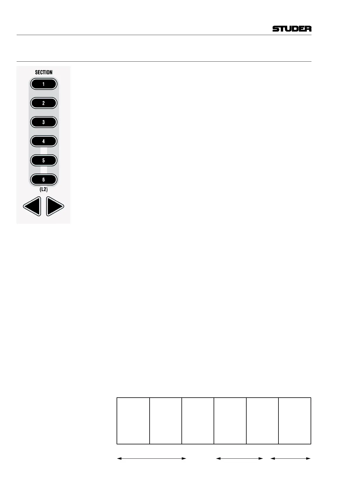
1.1.5 Scrolling
Most Vista installations will have more channels available in the DSP core
than there are physical faders on the console surface. Most manufacturers deal
with that fact by introducing ‘layers’: The console surface can be switched
in order to show the different layers, all of which making all DSP channels
available to the user. The Vista operating philosophy has modified this con-
cept. Rather than thinking of layers sitting on top of each other, we think
of the layers being arranged on a horizontal line. The ‘Layer’ is now called
‘Section’. The six sections are next to each other on an imaginary horizontal
line, as indicated by the ‘Section Navigator’ keys in the control bay.
As long as the user wants to switch to a specific section, there is no difference
in operation to the ‘layer’ concept. Changing to another section is accom-
plished by pressing one of the corresponding keys in the SECTION NAVIGATOR
area of the control bay (below right), or by pressing the arrow keys located
in each fader bay with SCROLL: SECTION set to ON (below left).
Information on which section is currently displayed is given by the illuminated
keys. Looking at the Graphical Controller with the ‘strip setup’ screen in the
foreground will also indicate the currently displayed section by putting a dark
background to the displayed channels.
The Difference from the Layer Concept
Rather than just switching to another section, it is possible to scroll through
the sections by pressing any arrow key (for this purpose, SCROLL: SECTION
has to be OFF on the fader bays). This will make the physical surface scroll
through all sections with a step size of one bay (10 channels). It is therefore
possible to move any channels close to the position of the operator, allowing
him to stay in the ‘sweet spot’ at all times. This concept can also be imagined
like moving a chair in front of an analog console. On Studer Vista, you move
the surface of an imaginary console six times larger than the physical console.
Which DSP channel is shown where on the desk is defined in the ‘strip setup’
dialog in the Graphical Controller (refer to chapter 4.4.7).
Desk Navigation Example Let’s assume a desk with 32 faders (between 22 and 42 possible in steps of
10). Since the desk can jump to six sections, this user can operate up to 6 × 32
DSP channels. Please note that it is possible to have the same DSP channel
visible in multiple places within the six sections.
Step 1 The user defines the order of the 186 DSP channels in the strip setup dialog
box in the GC. There he will find six empty sections with 32 placeholders,
each for a channel assignment.
The definition will most likely be made in such a way that the user starts with
a new section when he starts with new channel type, as shown below.
Section
1
(32 Channel Strips
to Occupy)
Section
2
Section
3
Section
4
Section
5
Section
6
(32 Channel Strips
to Occupy)
(32 Channel Strips
to Occupy)
(32 Channel Strips
to Occupy)
(32 Channel Strips
to Occupy)
(32 Channel Strips
to Occupy)
User occupies 70 Placeholders
with DSP Channels
‘Input Mono 1...70’
User occupies 48 Placeholders
with DSP Channels
‘Track Return 1...48’
42 Places with
DSP Channels
‘AUX Send’, ‘CGM’,
‘Master Outputs’