SCore Live
SCore Live 5Document generated: 20.09.13
DSP/Bridge Card Configurations
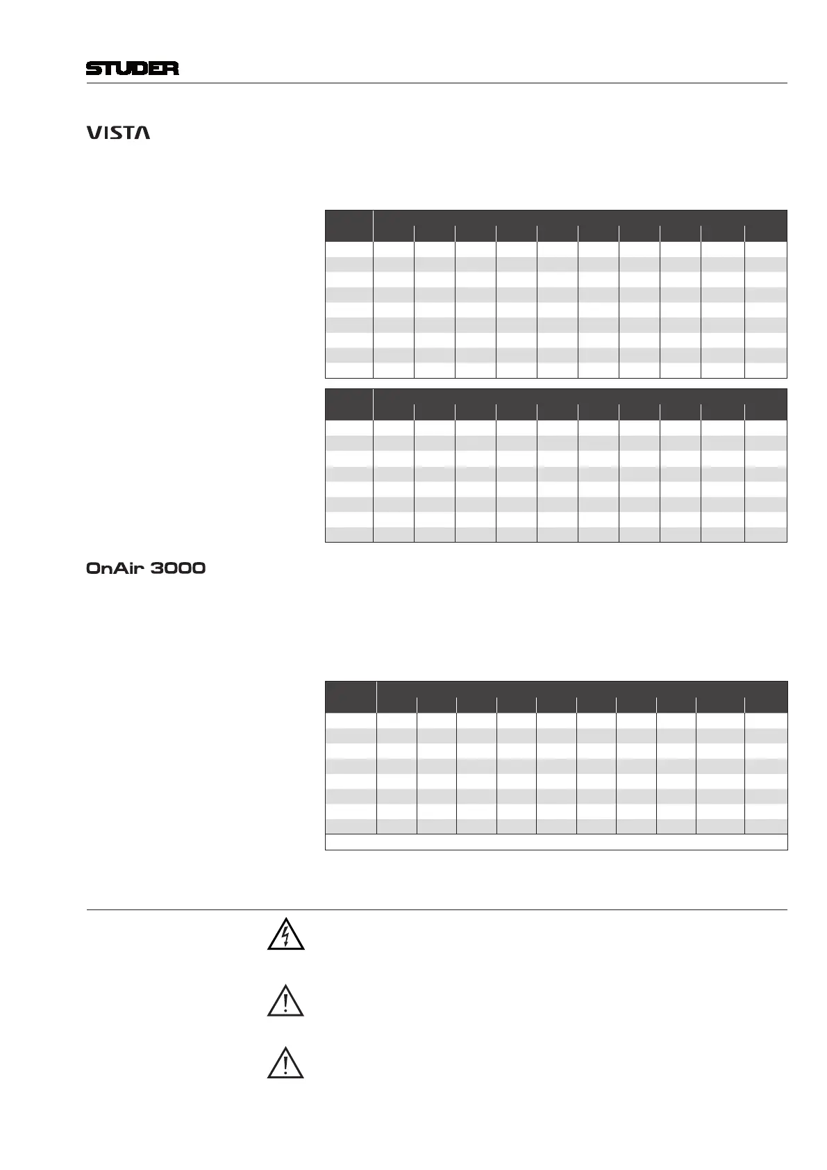
Nine normal ‘N’ and eight redundant ‘R’ (dual bridge card) configurations
are possible. It is recommended to use the slot order given in the tables below
for optimum thermal results. (For slot numbering refer to chapter 2.2).
‘N’ Setups (1 Bridge Card)
Config
Slot
1 2 3 4 5 6 7 8 9 10
N1
DSP Bridge
N2
DSP DSP Bridge
N3
DSP DSP DSP Bridge
N4
DSP DSP DSP DSP Bridge
N5
DSP DSP DSP DSP DSP Bridge
N6
DSP DSP DSP DSP DSP DSP Bridge
N7
DSP DSP DSP DSP DSP DSP DSP Bridge
N8
DSP DSP DSP DSP DSP DSP DSP DSP Bridge
N9
DSP DSP DSP DSP DSP DSP DSP DSP DSP Bridge
‘R’ Setups (2 Bridge Cards)
Config
Slot
1 2 3 4 5 6 7 8 9 10
R1
DSP Bridge Bridge
R2
DSP DSP Bridge Bridge
R3
DSP DSP DSP Bridge Bridge
R4
DSP DSP DSP DSP Bridge Bridge
R5
DSP DSP DSP DSP DSP Bridge Bridge
R6
DSP DSP DSP DSP DSP DSP Bridge Bridge
R7
DSP DSP DSP DSP DSP DSP DSP Bridge Bridge
R8
DSP DSP DSP DSP DSP DSP DSP DSP Bridge Bridge
DSP/Bridge Card Configurations
The DSP configuration vary with the number of I/O channels. The basic
configuration with two DSP cards offers the functionality of C10802. Con-
figurations up to C10804 may be operated without a fan unit as long as no
redundant bridge card (*) is used. For OnAir 3000 installations, the slot order
given below must be followed. (For slot numbering refer to chapter 2.2).
Config
Slot
1 2 3 4 5 6 7 8 9 10
C10802
DSP DSP *Bridge Bridge
C10803
DSP DSP DSP *Bridge Bridge
C10804
DSP DSP DSP DSP *Bridge Bridge
C10805
DSP DSP DSP DSP DSP *Bridge Bridge
C10806
DSP DSP DSP DSP DSP DSP *Bridge Bridge
C10807
DSP DSP DSP DSP DSP DSP DSP *Bridge Bridge
C10808
DSP DSP DSP DSP DSP DSP DSP DSP *Bridge Bridge
C10809
DSP DSP DSP DSP DSP DSP DSP DSP DSP Bridge
*Bridge = redundant Bridge card
1.2.3 Adjustments, Repair, Cleaning
Danger! All internal adjustments as well as repair work on this product must be per-
formed by expert technicians!
Replacing the Supply Unit The primary fuse is located within the power supply module and cannot be
changed. In case of failure, the complete power supply unit must be replaced.
Please ask your nearest Studer representative.
Cleaning Do not use any liquids to clean the exterior of the unit. A soft, dry cloth or
brush will usually do.


 To Next Page