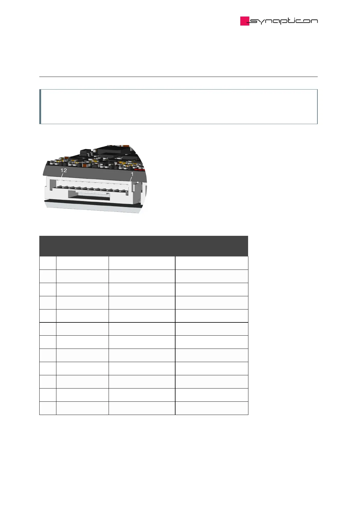
1.3.2.4.1.3.4 Analog IN
Note
Details about measuring Analog signals can be found in our system integration guideline: Connecting and
configuring analog inputs
Pin
#
Default Setting * Object Mapping
1 –
2 Analog Input 1 - Connect to Ground **
3 Analog Input 1 + Single-ended 0-10 V Analog input 1 (0x2401)
4 Ground
5 Analog Input 2 - Connect to Ground **
6 Analog Input 2 + Single-ended 0-10 V Analog input 2 (0x2402)
7 5 V ***
8 10 V ****
9 Analog Input 3 - Differential ±5 V Analog input 3 (0x2403)
10 Analog Input 3 + Differential ±5 V Analog input 3 (0x2403)
11 Analog Input 4 - Differential ±5 V Analog input 4 (0x2404)
12 Analog Input 4 + Differential ±5 V Analog input 4 (0x2404)
* All Analog Inputs can be configured as single-ended 0-5 V, 0-10 V, 0-20 V or differential ±5 V, ±10 V
independently.
Upon request only, please contact sales@synapticon.com