EasyManuals Logo

SYNAPTICON CIRCULO 7 User Manual

SYNAPTICON CIRCULO 7
887 pages
To Next Page IconTo Next Page
To Previous Page IconTo Previous Page
Page #843 background imageLoading...
Page #843 background image
4.1.4.2 Safety brake output
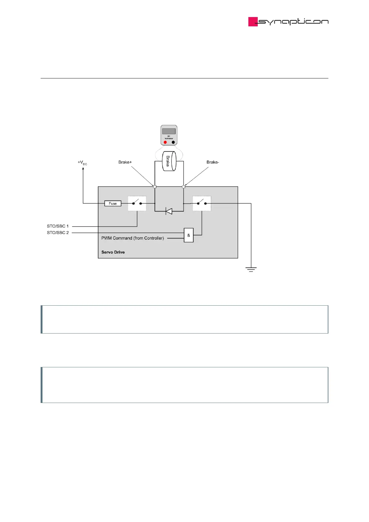
The image below shows the safety brake circuit. The PWM signal is connected to a switch that is connected to
Ground (GND). So for controlling the voltage level, it is generating a PWM signal on the GND side.
Note
The PWM signal is generated on the Brake- side.
For measuring the safety brake output voltage, B+ and B- must be connected to the voltmeter. Measuring the
voltage between B+ and GND or B- and +V will result in a wrong value.
Note
The brake or a similar electrical load has to be connected to the brake outputs when measuring the
output voltage. Without a load, the multimeter will show an incorrect input DC voltage.
In
Synapticon Documentation
© 2021 Synapticon GmbH | Daimlerstraße 26 | D-71101 Schönaich Documentation v 4.11.0 | Built 2021-07-23 843/887

Table of Contents

Questions and Answers:

Question and Answer IconNeed help?

Do you have a question about the SYNAPTICON CIRCULO 7 and is the answer not in the manual?

SYNAPTICON CIRCULO 7 Specifications

General IconGeneral
BrandSYNAPTICON
ModelCIRCULO 7
CategoryServo Drives
LanguageEnglish

Related product manuals