EasyManuals Logo

SYNAPTICON CIRCULO 7 User Manual

SYNAPTICON CIRCULO 7
887 pages
To Next Page IconTo Next Page
To Previous Page IconTo Previous Page
Page #841 background imageLoading...
Page #841 background image
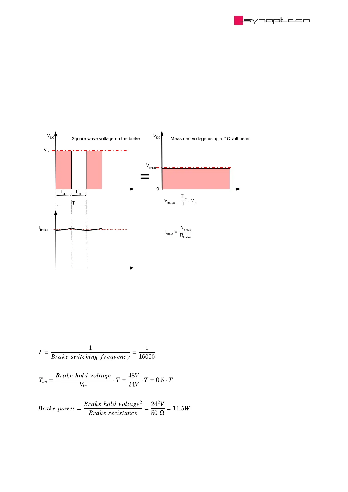
4.1.4 Measuring the brake output voltage
The brake voltage is a square wave signal 16 kHz, 32 kHz or 64 kHz (configurable in subitem 2004:11). A PWM
method is used for applying the appropriate voltage to the brake output.
The brake output voltage does not have a negative component. It is connected to an inductor which results in
a constant current.
Example
V (Input DC voltage) = 48 V
Brake switching frequency = 16 KHz
Brake hold voltage = 24 V
Brake resistance = 50 Ω
in DC
Synapticon Documentation
© 2021 Synapticon GmbH | Daimlerstraße 26 | D-71101 Schönaich Documentation v 4.11.0 | Built 2021-07-23 841/887

Table of Contents

Questions and Answers:

Question and Answer IconNeed help?

Do you have a question about the SYNAPTICON CIRCULO 7 and is the answer not in the manual?

SYNAPTICON CIRCULO 7 Specifications

General IconGeneral
BrandSYNAPTICON
ModelCIRCULO 7
CategoryServo Drives
LanguageEnglish

Related product manuals