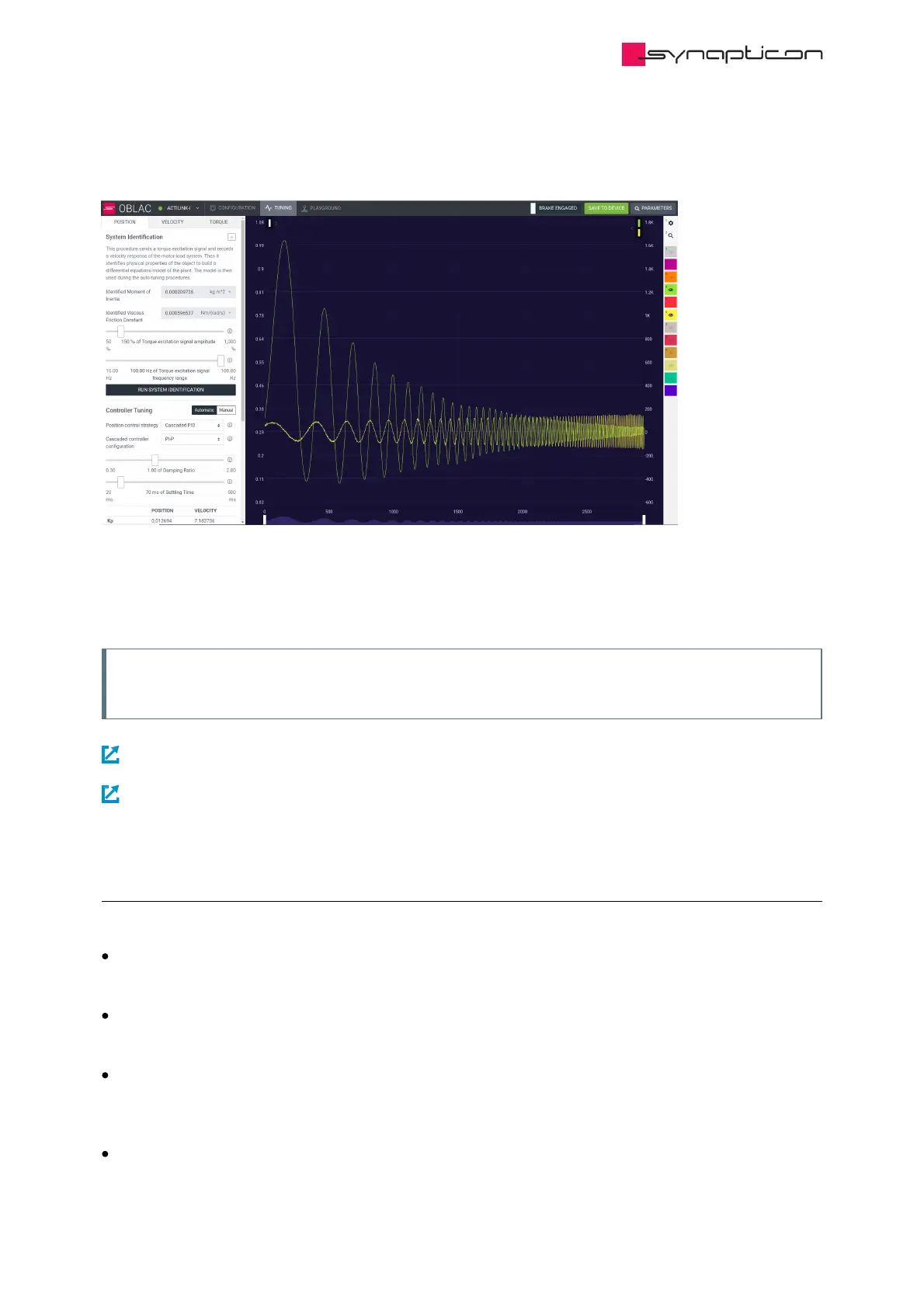
communication delay. As a result, higher frequencies are included into the model. An example of high
frequency range can be seen in the image below:
When the System Identification was successfully executed the dialog collapses to a button “Rerun System
Identification”. A set of default controller gains is calculated and the options for position autotuning are
displayed instead.
Note
If the electromechanical system was changed the identification should be repeated.
NEXT STEP: Position Autotuning Calculate controller gains that result in a specified position control-loop performance.
NEXT STEP: Velocity Autotuning Tune the velocity loop with Velocity Auto-Tuning for Cyclic Synchronous
Velocity mode.
2.4.2.4.4 F.A.Q.
# Can I define other velocity/torque units in the custom firmware?
The system identification is possible only with default units.
# Do I have to repeat system identification after attaching a load to the system.
It is recommended to repeat the procedure.
# What if my encoder has a low resolution?
The velocity signal used in system identification might have multiple zeros that may result in an incorrect
model.
# The system goes to overcurrent or the software resets during the system identification.
Check the configuration parameters and compare them to the official motor and sensor datasheet.