3.1.9.1.158 0x60FD Digital inputs
Bit 0: Shows Negative Limit Switch Status (1 = Active, 0 = Inactive )
Bit 1: Shows Positive Limit Switch Status (1 = Active, 0 = Inactive )
Bit 2: Shows Home Switch Status (1 = Active, 0 = Inactive )
Bit 3: Shows Interlock Status (1 = Drive cannot be enabled, 0 = Drive can be enabled)
Bit 4 to 15: Reserved
The manufacturer-specific bits (16 to 31) show the state of the Drive's digital inputs.
Bit 16: Digital input 1
Bit 17: Digital input 2
:
Bit 31: Digital input 16
For example, if only Digital input 1 is high (and bits 0 to 3 are low), then object value will be 65536 (0x10000)
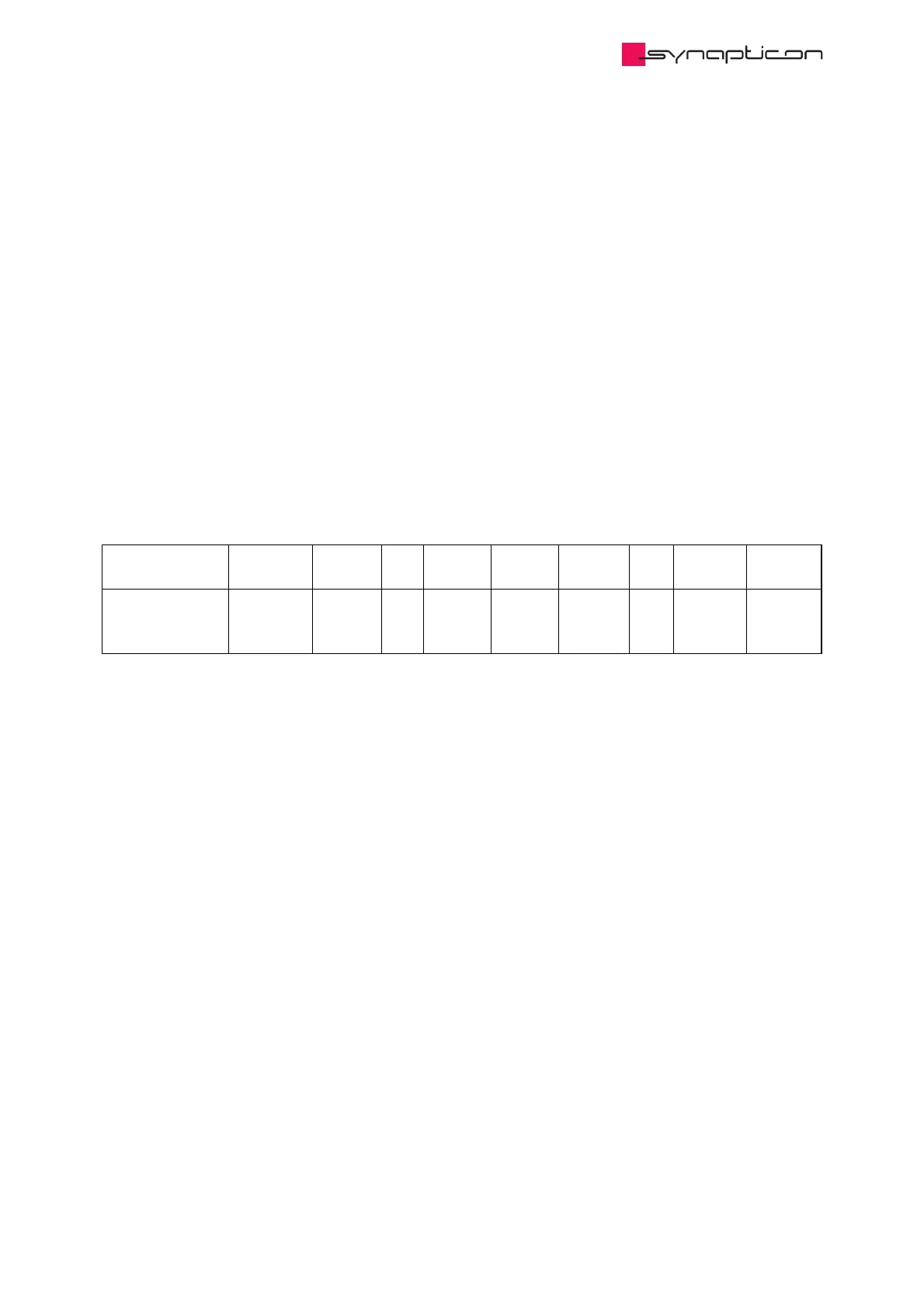
Name Index:Sub Type Bit
Size
Min
Data
Max
Data
Default
Data
Unit Access PDO
Mapping
Digital inputs 0x60FD:0 UDINT 32 0 readonly
(default)
Transmit
PDO
(Inputs)