TractionPedalNeutralAdjustment(continued)
g288435
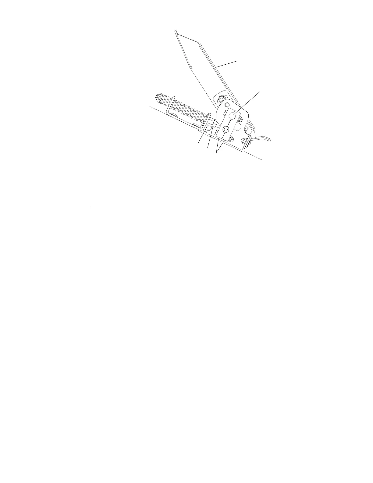
Figure192
1.Tractionpedal4.Locknut
2.Tractionpedalshaft5.Springshaft
3.Clampblocks
5.Onthebargraphinthescreen,thepositionindicatorbarshouldbebetween
NRandtheNF .Also,thereverseswitchandforwardswitchiconsshould
bothbeopen.
Toadjustthepositionindicatorbarlocation:
A.Removescrewssecuringsteeringcoverandmovesteeringcoverup
steeringcolumntoaccesstractionpedalassembly(seeTractionPedal
(page7–37)).
B.Loosenhexnutthatsecuresneutralspringadjustment(Figure192).
C.Slowlyrotatethespringshaftwhilewatchingtheswitchicons(Figure
192).Whenoneoftheswitchiconsclose,stoprotatingandmarkthe
shaftposition.Thenslowlyrotatetheshaftintheoppositedirectionuntil
thesecondswitchiconclosesandmarktheshaftposition.
D.Slowlyrotatethespringshafttothemid−pointofthetwoshaftpositions.
Tightenthehexnuttosecuretheadjustment.Atthissetting,theposition
indicatorbarshouldbebetweentheNRandtheNF.Also,theneutral
voltagevalueshouldbewithin0.02Vofthemidpointvoltage.
Note:Whenadjustingtractionpedal,voltagevaluesshouldbesimilarto
valuesshown(Figure191).
E.Installsteeringcover.
6.Afteradjustingthetractionpedalforneutral,andbeforereturningthe
machinetoregularservice,calibratetractionpedalpositionsensor(see
TractionPedalPositionSensorCalibration(page6–51)).
ElectricalSystem:Adjustments
Page6–50
Groundsmaster
®
5900&5910
16227SLRevB
 Loading...


