BladeSpindleAssembly(Figure333)(continued)
g299695
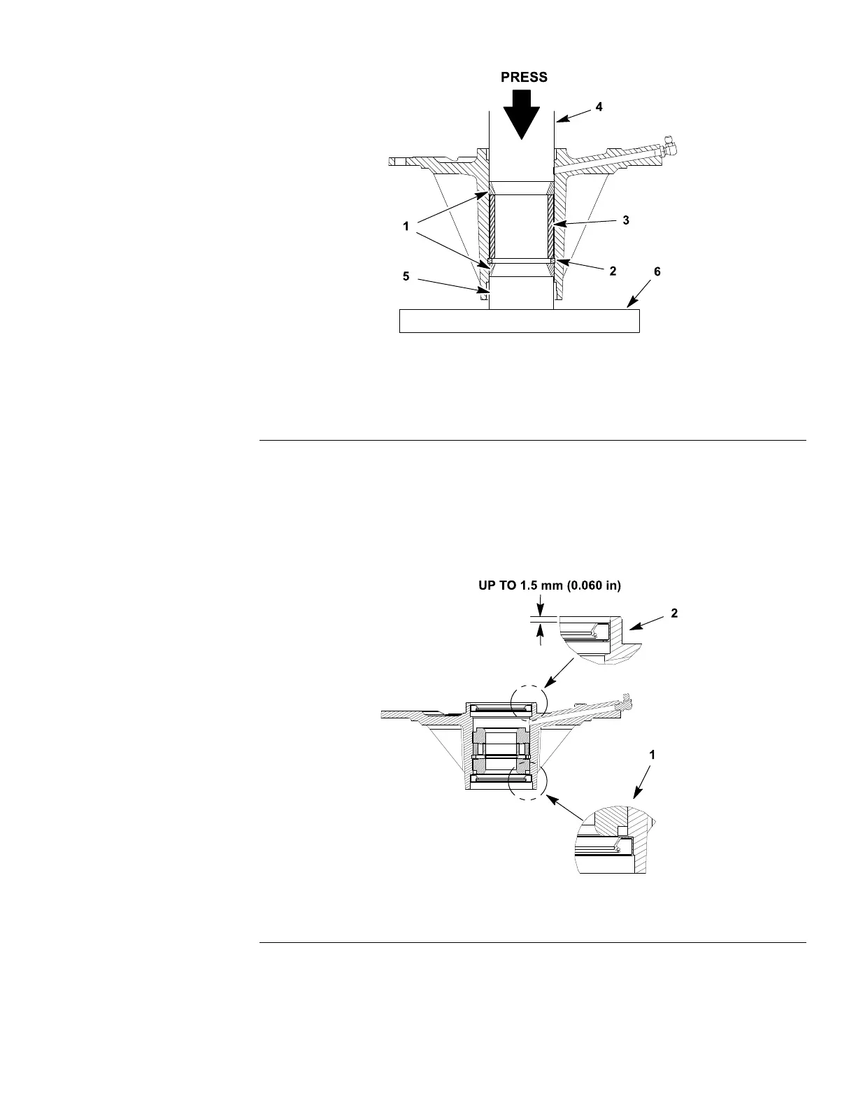
Figure335
1.Bearingcups4.Arborpress
2.Largesnapring
5.Support
3.Largeouterspacer6.Arborpressbase
4.Usinganarborpress,pushthebearingcupsintothetopandbottomofthe
spindlehousing.Thetopbearingcupmustcontacttheouterbearingspacer
previouslyinstalled,andthebottombearingcupmustcontactthelargesnap
ring.Makesurethattheassemblyiscorrectbysupportingtherstbearing
cupandpressingthesecondcupagainstit(Figure335).
5.Packthebearingconeswithgrease.Applyalmofgreaseonlipsofoil
sealsandO−ring.
g299696
Figure336
1.Bottomsealinstallation2.Uppersealinstallation
6.Installlowerbearingconeandgreasedoilsealintobottomofspindle
housing.Note:Thebottomsealmusthavethelipfacingout(down)(Figure
336).Thissealinstallationallowsgreasetopurgefromthespindleduring
thelubricationprocess.
Groundsmaster
®
5900&5910
Page8–19
CuttingDecks:ServiceandRepairs
16227SLRevB
 Loading...


