November, 1998
30
Dismounting/Repair Brewing SystemService Manual FB50/55/5100/5500
9.3Functional Descriptions
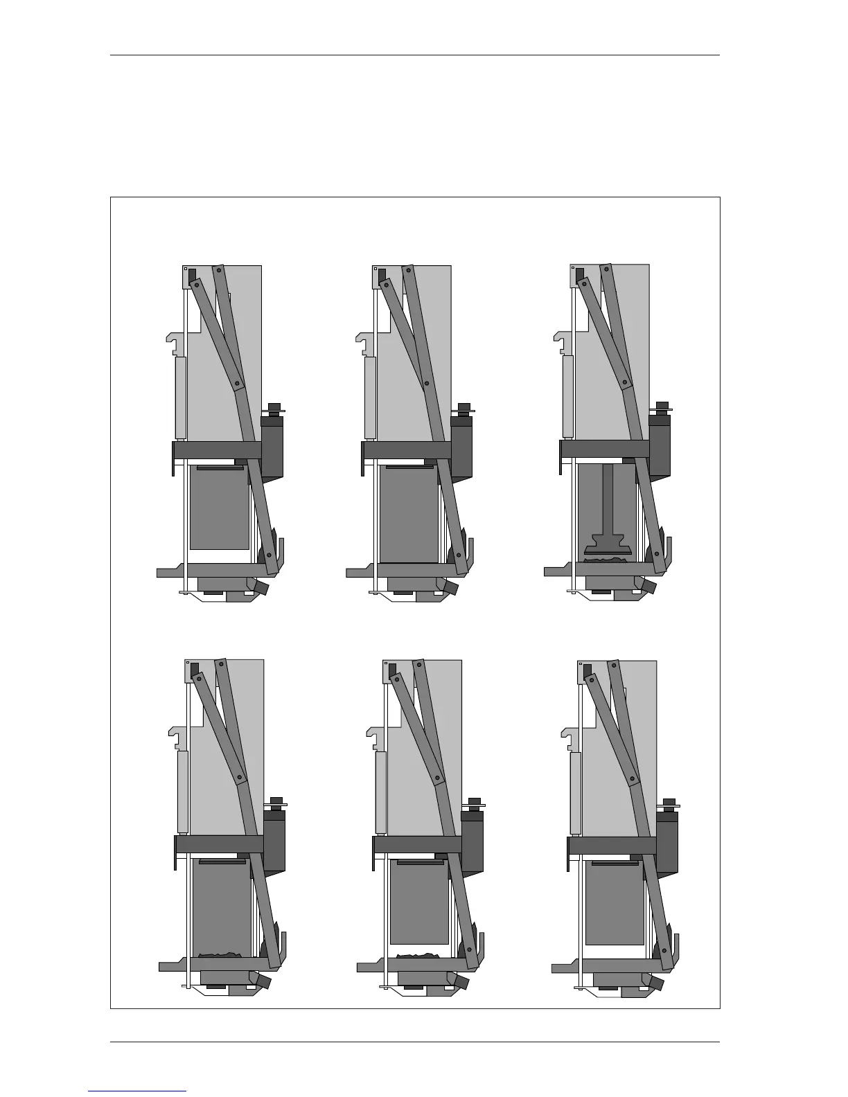
9.3.1Schematic Illustration of the Brewing Process
Fig. 4
Plunger in upper position
Fig. 6
Scraper in end position
Fig. 5
Brewer cylinder opened
Fig. 1
Brewer cylinder in start position
Fig. 2
Brewer cylinder closed
Fig. 3
Plunger in lower position
Schematic Illustration of the Brewing Process - Starting position front