Symbol Description
Segment numbers and isolation switch open.
Segment numbers and isolation switch closed.
Indicates voltage and frequency are in range.
Indicates voltage or frequency are not in range.
Own LS-5 device number.
Other LS-5 device numbers.
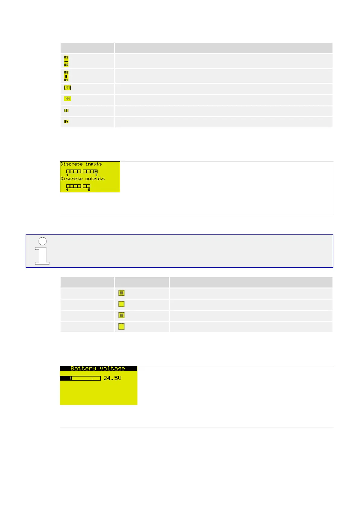
5.2.3.12 Discrete Inputs/Outputs
Fig. 124: Discrete inputs/outputs screen (example)
This screen displays discrete inputs' and discrete outputs' status.
The
congured logic for the discrete input "N.O./N.C." will determine how the LS-5 reacts
to the state of the discrete input. If the respective DI is congured to N.O., the unit reacts
on the energized state; if it is congured to N.C., it reacts on the de-energized state.
Type Symbol State
Input energized
de-energized
Output relay activated
relay de-activated
5.2.3.13 Analog Input
Fig. 125: Battery voltage screen (example)
This screen displays the battery voltage.
247LS-5 v2 Series37650
5 Operation
5.2 Front Panel Access

 Loading...


