1
Use the Ethernet CAT 5 cable which is supplied with the DPC-RS-232 converter. The
maximum cable length must not exceed 0.5 m.
For a continuous operation with the direct conguration cable DPC-RS-232 (e.g. remote
control of controller), it is required to use at least revision F (P/N 5417-557 Rev. F) of the
DPC-RS-232. When using a DPC-RS-232 of an earlier revision, problems may occur in
continuous operation. The shield connector (6.3 mm tab connector) at the DPC-RS-232 of
revision F (P/N 5417-557 Rev. F) and above must be connected to ground.
3.4
CAN Bus Interface
Pin assignment
Terminal Description A
max
56 CAN-L N/A
57 CAN-H N/A
Tab. 10: Pin assignment
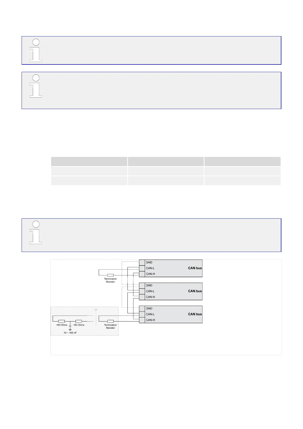
Topology
Please note that the CAN bus must be terminated with a resistor, which corresponds to
the impedance of the cable (e.g. 120 Ohms, 1/4 W) at both ends.
The termination resistor is connected between CAN-H and CAN-L (╚═▷ Fig. 69).
Fig. 69: CAN bus - termination
For very critical EMC conditions (many noise sources with high noise levels) and for high
transmission rates we recommend to use the 'Split termination concept' as shown.
• Divide the termination resistance into 2x60 Ohms with a center tap connected to
ground via a capacitor of 10 to 100 nF (╚═▷ Fig. 69).
71LS-5 v2 Series37650
3 Installation
3.4 CAN Bus Interface

 Loading...


