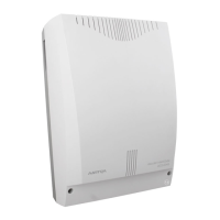
Ascotel IntelliGate 2025/2045/2065
964 Generation Change Part 8
Fig. 8.3: Warning plate on the PBX
Warning:
The processor card and/or RAM card can be damaged by electrostatic
discharge. Always touch the earthed metal cage of PBX before touching
the cards!
Procedure
1. If necessary carry out the preparations as described in the Chapter "System
Upgrade 2065", page 959.
2. Switch off the PBX. When using a UPS disconnect the battery first, then dis-
connect the PBX and any external Auxiliary Terminal Power Supply (ATPS)
from the 230 V mains.
3. Remove the PBX cover.
4. Unscrew the screws on the screening strip and pull out the processor card
complete with screening strip.
5. Press the side locks on the RAM card outwards and pull out the RAM card (see
Fig. 8.4).
6. Take the new RAM card out of the ESD protective sleeve and insert it. The
notches on the RAM card prevent it from being inserted incorrectly.
7. Press the side locks inwards until they click into place.
8. Wrap the RAM card in the ESD protective sleeve.
9. Insert the processor card. Make sure the card is lying in the lower guide slot
of the metal cage and that the ends of the screening strip are flush against
the edge of the metal cage once the card has been inserted.
10. Screw the screening strip to the metal cage using the 2 screws.
11. Fit the housing cover.
12. Connect the PBX and any ATPS system to the 230 V mains, then connect the
UPS battery where applicable.
1
2
haz1254aaxxa0
haz0001aaxxa0

 Loading...