Gen II User Manual
7-13 – Main Rotor Track & Balance Chapter 7 Revision 3.00, Apr 2020
Tab Adj Decimal set to “3”
Rotors, a single rotor is chosen.
Four conditions have been entered for this job, “GROUND”, “HOVER”, “80 KTS”, and
“120KTS”. Both track and vibration will be measured and recorded for this setup.
Press [OK] to proceed to the next screen.
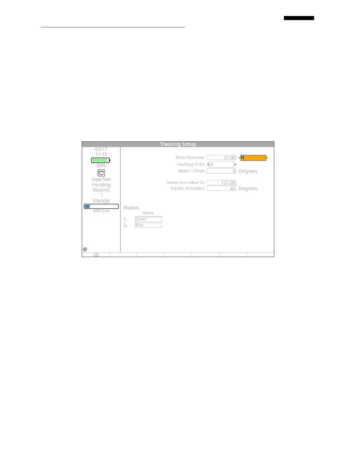
7.1.6.2. – Tracking Setup Screen
Enter “37.00” in the first block using the keypad.
Select “ft” for units of rotor diameter.
Select “in” for the display units of lead/lag data.
Enter “0” Degrees for the Blade 1 Offset.
Enter “121.00” for the Inches to Mast CL.
Enter “45” Degrees for the Tracker Inclination.
Enter “Green” & “Blue” for the individual main rotor blades
 Loading...