Gen II User Manual
7-14 – Main Rotor Track & Balance Chapter 7 Revision 3.00, Apr 2020
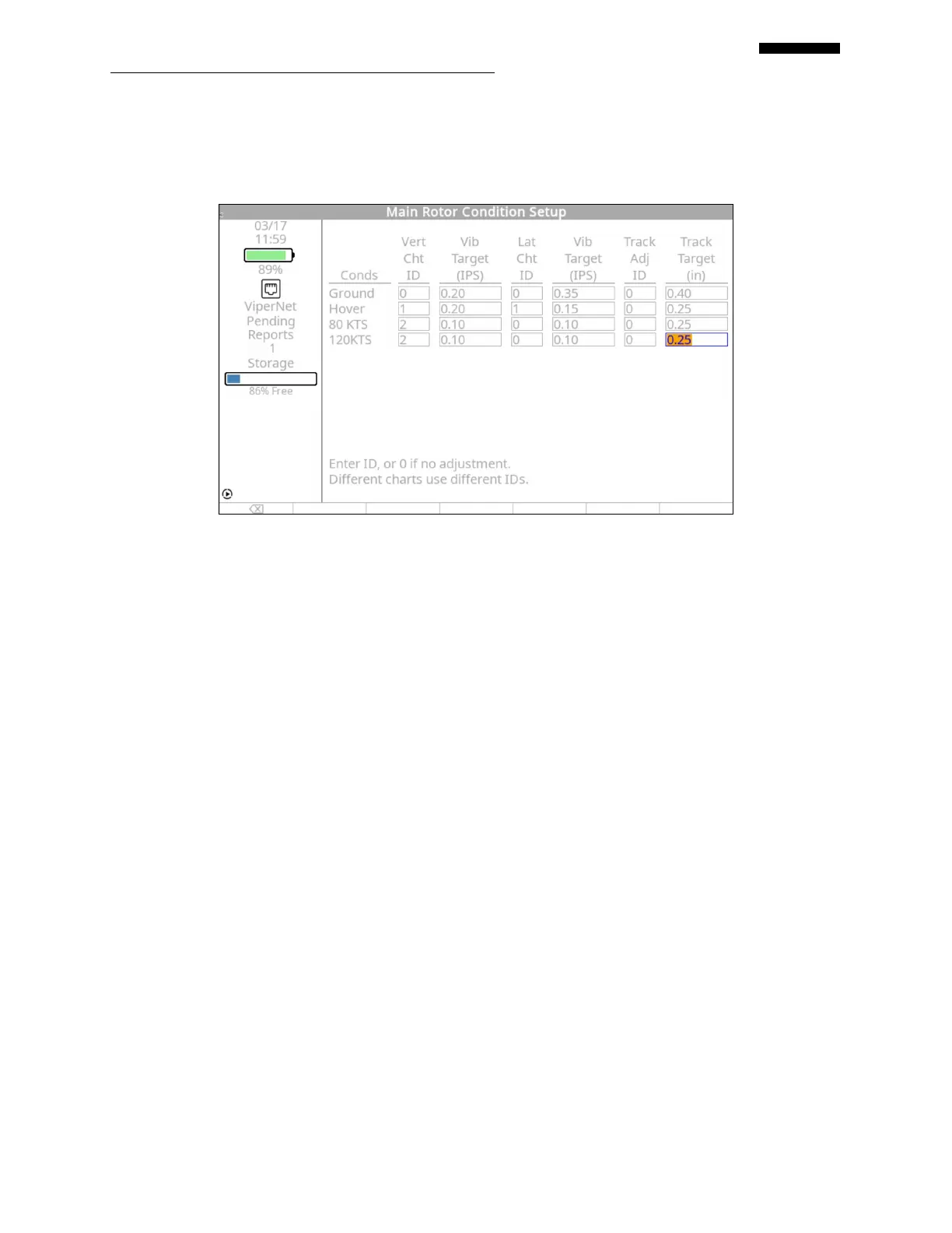
7.1.6.3. – Main Rotor Conditions Setup
Use the sample polar charts in paragraph 7.1.6. In the “Main Rotor Conditions Setup” screen
above, two vertical charts and one lateral chart have been identified. The first vertical chart, ID
number “1”, will be used for a vertical measurement in hover only, while the second vertical
chart, ID number “2”, is for the average vertical measurement of both “FLT 80” and “FLT120”.
One lateral chart has been identified for the lateral measurement in “Hover” only. The vibration
Target for Vertical measurements has been set at 0.20 IPS for Ground and Hover, and set at 0.10
IPS for 80 - 120 KTS. The Vibration Target for Lateral measurements has been set at 0.35 IPS
for Ground, 0.15 IPS for Hover, and 0.10 for FLT 80-120KTS. The Track split target is set at
0.40 inch for Ground, and 0.25 for Hover-120 KTS.
This main rotor setup will not use the tracking information measured by the analyzer for any
corrections. It will be for user reference only.
When completed, press [OK] to continue.
7.1.6.4. – Main Rotor Adjustment Symbol and Solution Logic Setup
 Loading...