Gen II User Manual
7-15 – Main Rotor Track & Balance Chapter 7 Revision 3.00, Apr 2020
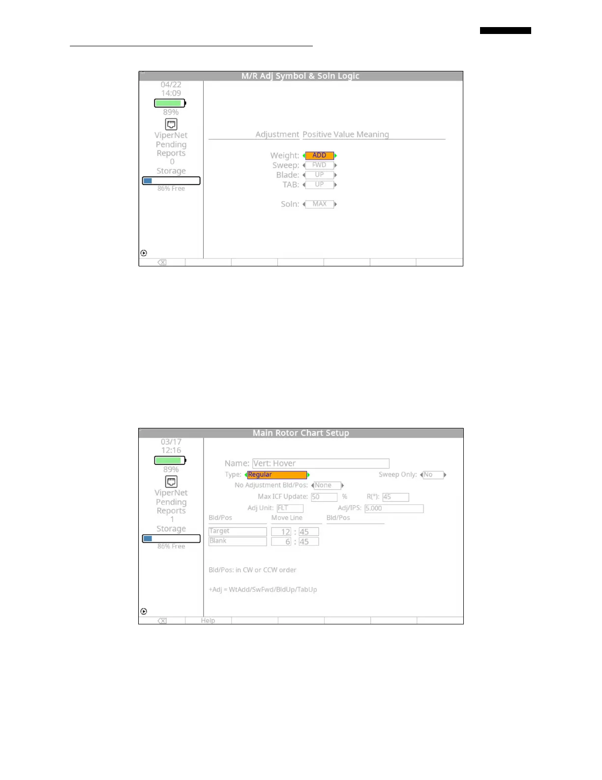
In the “Main Rotor Adj Symbol & Soln Logic” setup screen above, the positive numeric value in
a solution screen has been identified as ADDING weight, sweeping a blade FWD , moving a
blade UP using either pitch change links or tabs. The solution logic has been set to “MAX” and
will present the solution related to the highest vibration readings attained for the vertical and
lateral sensors.
Press [OK] to continue.
7.1.6.5. – “Vertical: Hover” Chart Definition
The “Vert: HOVER” chart setup screen appears first. Use the vertical vibration chart in
paragraph 7.1.6, to complete the steps below and properly define this chart.
 Loading...