Gen II User Manual
7-16 – Main Rotor Track & Balance Chapter 7 Revision 3.00, Apr 2020
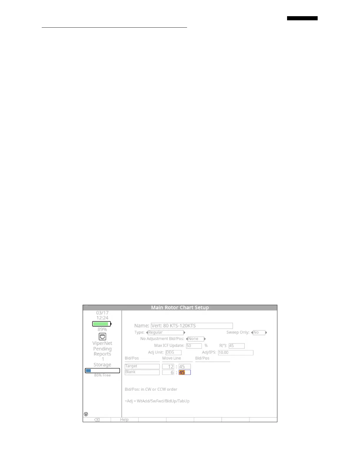
The name of the chart, “Vert: HOVER”, has been automatically entered from the “Main
Rotor Conditions Setup” screen and is non-editable.
The chart type is “Regular”.
This chart uses no sweep adjustments, and is therefore left as “No”.
No Adjustment Blade/Pos. is left as “None”.
Max ICF Update is “50” %.
Rotation is “45” degrees.
The type of adjustment applied in accordance with this chart is pitch change link in flats;
therefore “FLT” has been entered.
The influence co-efficient for the pitch change links is “5.0” flats per 1.0 IPS vibration.
The Bld/Pos names entered from the chart are “TARGET” and “BLANK”.
The “MoveLine” for moving the “TARGET” blade up is “12:45”.
The “MoveLine” for moving the “BLANK” blade up is “6:45”.
When completed, press [OK] to continue.
7.1.6.6. – “Vertical: 80 KTS – 120KTS” Chart Definition, Example 1
 Loading...