Gen II User Manual
7-30 – Main Rotor Track & Balance Chapter 7 Revision 3.00, Apr 2020
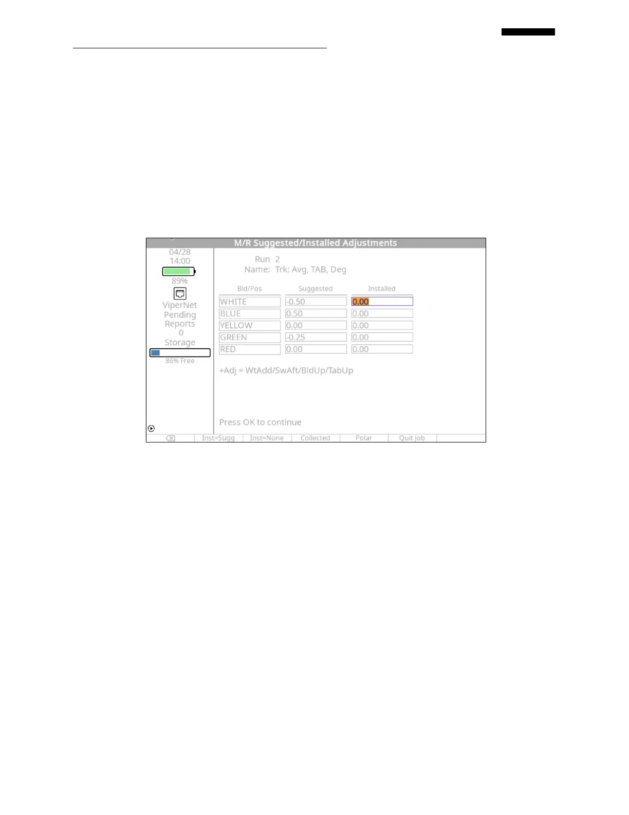
– Example Solution Screen #3
The last correction given for our sample job is for the Track adjustment using trim tabs. The
solution type for this adjustment is degrees on the trim tab.
NOTE
The analyzer will attempt to give solutions that “resolve to zero” in all cases. This may nullify the
ability to make some adjustments with any degree of accuracy. If this occurs, it is the user’s
responsibility to adjust the amount either up or down to achieve a quantifiable adjustment.
Remember that the analyzer will update the influence co-efficient between every run based on the
vibration results from the previous adjustment.
Once the adjustment has been made, press [OK] proceed to the Run 2: Select Condition Screen.
Repeat the data acquisition and solution application process to verify the adjustments have
brought vibration and track readings below limits.
After all vibration and track readings are below limits, the screen shown below will be displayed.
To end the job press [F5] “Quit Job”. This will mark the job as complete and return you to the
Main Menu.
 Loading...