About Instrument Calibration
MC4 User Guide 143
3. The actual test is done automatically: MC4 slowly increases
the input signal until the switch actuates and continues by de-
creasing the input signal until the switch deactuates. MC5’s
screen displays the obtained data as the test advances.
4. How the results are accepted depends on the procedure set-
tings of the instrument at hand:
• If
Automatic Calibration Point Acceptance
is set
(checked), the actuating and deactuating points of the
current switch cycle are saved automatically. Automatic
acceptance settings are presented in chapters Proce-
dure Data Page on page 165 and Accepting Calibra-
tion Points Automatically on page 178.
• If
Automatic Calibration Point Acceptance
is not
set, accept the point using F3/
Accept
Function Key.
5. A calibration run can include several switch cycles. The
amount of switch cycles is defined among the instrument's
procedure data. As long as more switch cycles need to be
done, MC4 automatically starts a new cycle (step 3).
6. When all switch cycles are done, i.e. the calibration run is
ready, save or reject the results as described in chapter A
Calibration Procedure Using MC4 on page 130.
7. Either do another calibration run, adjust the instrument or end
the calibration by selecting F1/
Menu
,
Close
.
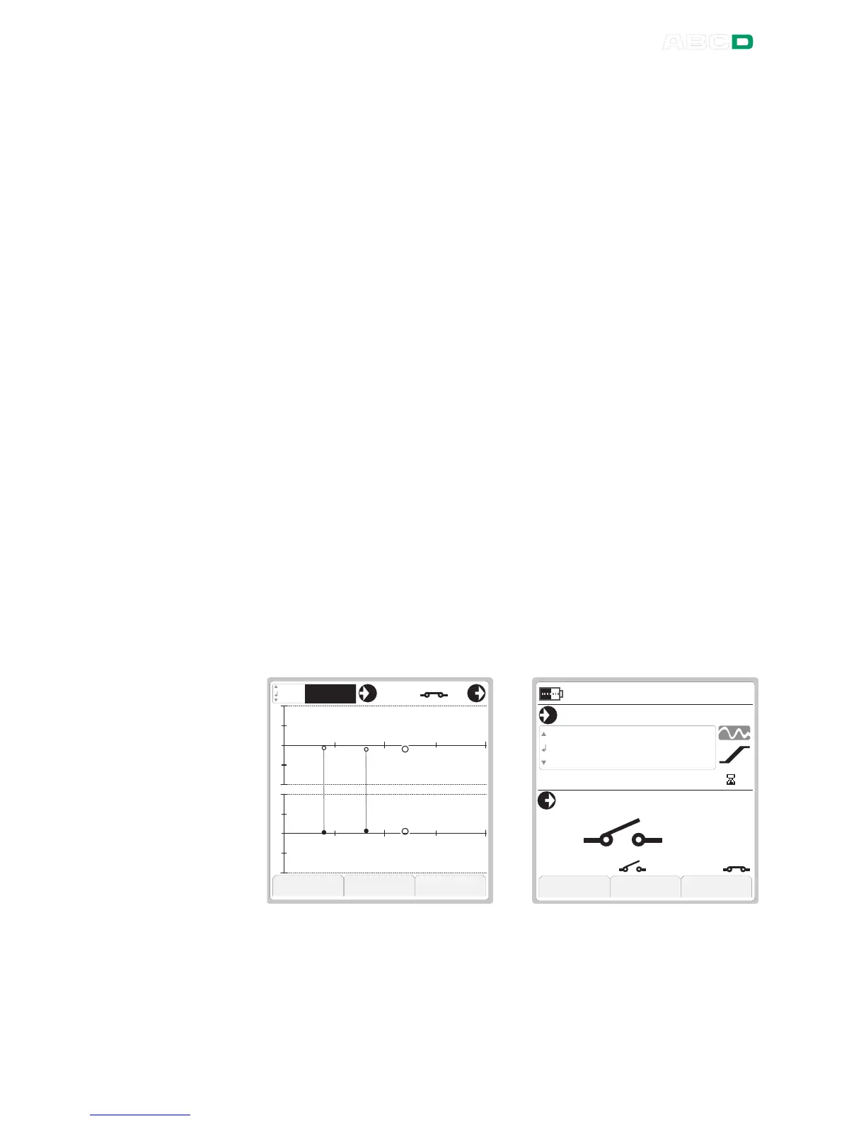
The pictures below present the calibration windows Graphics view
(left) and Numeric view (right) for switches:
In Graphics view there are two graphs. The upper one shows the er-
ror for the actuating point and the lower one the error of the deactu-
ating point. The Numeric view displays the measured actuating point
and deactuating point just above the Function Keys.
 Loading...


