82.3-0000010 OM
100
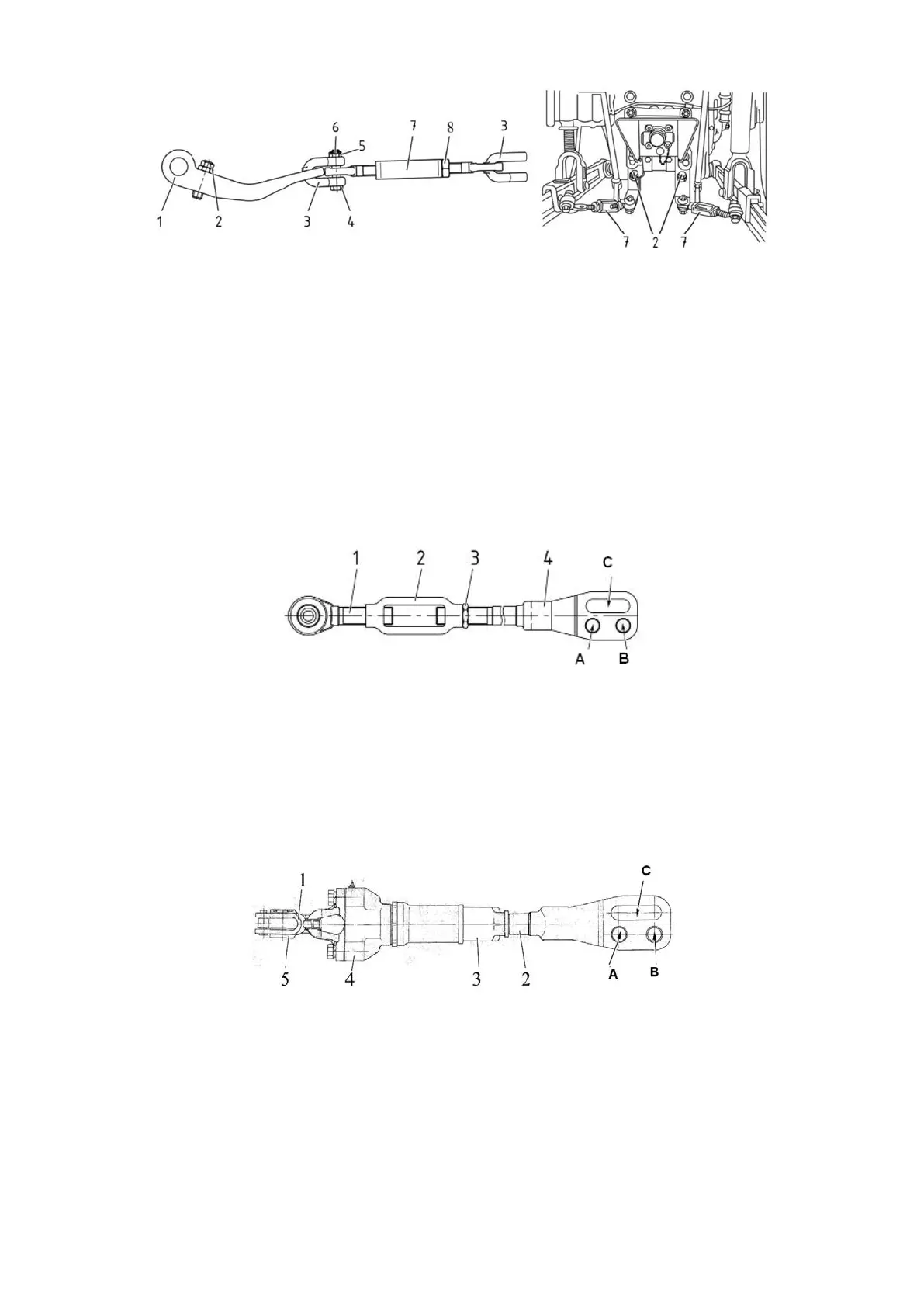
1 – bracket; 2 – bolt; 3 – clevis; 4 – bolt; 5 – nut; 6 – cotter pin; 7 – buckle; 8 – locknut.
Figure 4.3.6 – Inner buckle
ATTENTION: WHEN CHANGING THE LENGTH OF THE LIFTING ROD IT IS
NECESSARY TO READJUST THE LOCKING OF THE BUCKLES IN TRANSPORT AND
WORKING POSITIONS. NONFULFILLMENT OF THIS REQUIREMENT CAN LEAD TO
BREAKAGE OF THE LIMITING BUCKLES OR OTHER BREAKAGES!
4.3.3.2 Lifting rod
The tractor can be equipped with two types of lifting rods: screw lifting rod and gear lifting rod.
One of the three configurations of lifting rod pairs can be installed against order:
- two gear lifting rods;
- one gear lifting rod (on the right side in the direction of tractor travel) and one screw
lifting rod;
- two screw lifting rods.
The screw lifting rod is shown in Figure 4.3.7.
1 – screw with hinge joint assembly; 2 – buckle; 3 – locknut; 4 – yoke.
Figure 4.3.7 – Screw lifting rod
Adjustment of screw lifting rod length shall be made as follows:
- unscrew locknut 3;
- change the lifting rod length by turning buckle 2 clockwise or counterclockwise;
- having adjusted the lifting rod length, lock the screw coupling with locknut 3.
The gear lifting rod is shown in Figure 4.3.8.
Adjustment of gear lifting rod length shall be made by turning handle 5 clockwise or
counterclockwise.
1 – handle; 2 – yoke; 3 – pipe; 4 – housing; 5 – clevis.
Figure 4.3.8 – Gear lifting rod
The length of lifting rods (either screw lifting rod or gear lifting rod) is adjusted within the lim-
its of 425…520 mm. In ex-works condition the lifting rods are adjusted for the length of 475 mm.
To accelerate adjustment of the lifting rod length, two bores (А and B in Figures 4.3.7 and
4.3.8) are provided on its yoke for pin installation. To copy the contour of processed field during
operation with wide-cut implements and to avoid lifting rod damage, connect the lifting rods with
lower links using grooves (В in Figures 4.3.7 and 4.3.8). The lifting rod yoke grooves shall be
located behind the bore as to the direction of tractor travel in order to avoid lifting rod damage.