82.3-0000010 OM
109
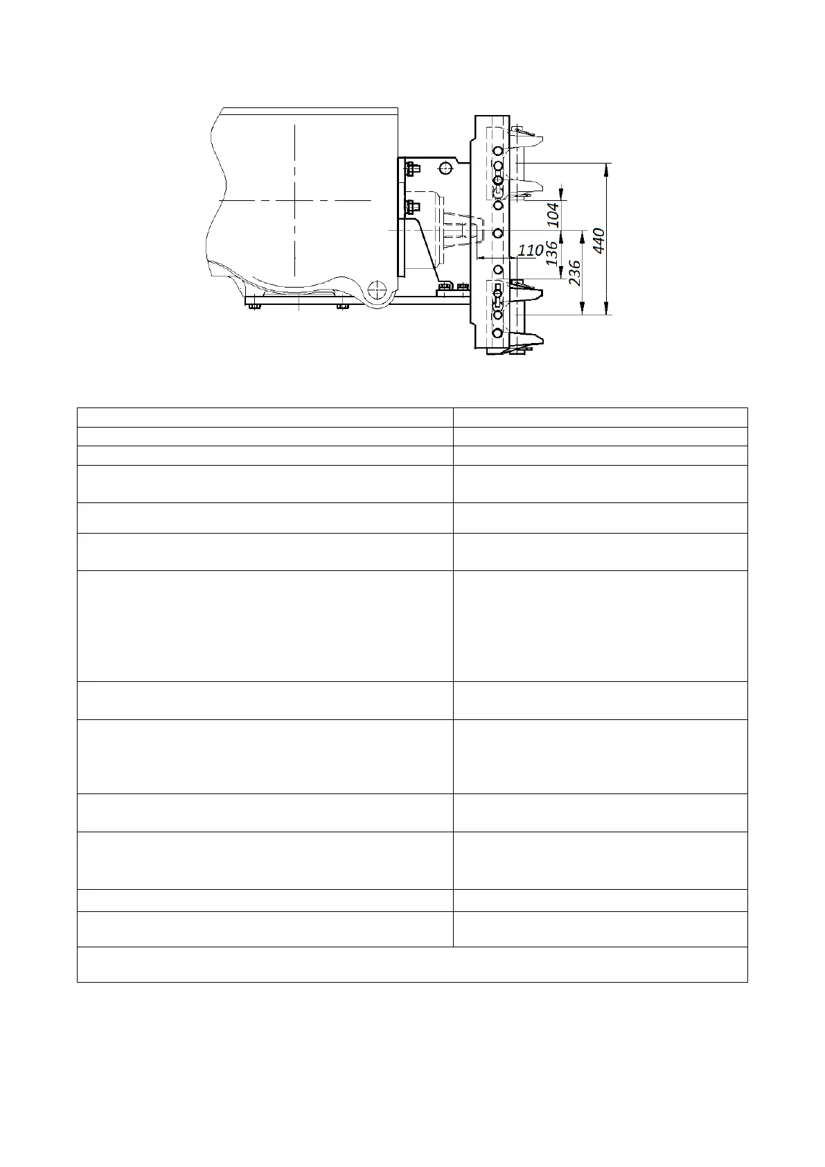
4.4.3 Tow hitch with non-rotating yoke 1321-2707113-A
Figure 4.4.2 – Installation variant scheme of non-rotating yoke 1321-2707113-A
(main bottom and possible uppermost positions are shown)
Table 4.4.2 – Basic parameters and coupling dimensions of non-rotating yoke
2 Variant and designation
Guide grooves of the bracket attached to
rear surface of rear axle body
Nonrotational, height adjustable
1)
For connection of trailed and semi-trailed
agricultural machines
а) kingpin diameter
b) yoke gap height
c) yoke gap depth from kingpin axis
d) yoke position for machines driven from rear PTO
40
85
70
Only bottom position as shown in figure
7 Type of trailing appliance for connection to yoke
8 Vertical load in hitch point, equivalent to weight,
kg, not more than:
- for lowermost position;
1820
9 Relative calculated value of axial forces (D), kN,
not more than
10 Safety device type
10.1 Connection point of safety device to the tractor
Safety chain (rope)
2)
Bores in guide grooves of mounting bracket
11 EU certificate type, No
12 Certificate of Customs Union Technical Regula-
tion, No
–
1)
The height should be set equal to the height of the trailer eye.
2)
ATTENTION: IT IS FORBIDDEN TO PUT YOKE TO POSITIONS WHERE ITS BODY
JUTS OUT OF THE MOUNTING BRACKET END (UP OR DOWN) FOR MORE THAN 20 MM!
ATTENTION: TAKING INTO ACCOUNT THE RELATIVE CALCULATED VALUE OF
AXIAL FORCES (D) PERMISSIBLE FOR THIS ELEMENT, THE MASS OF THE TRAILER,
THE SEMI-TRAILER OR THE MACHINE TO BE ATTACHED TO THE NON-ROTATING
YOKE SHALL NOT EXCEED 12 TONS!