82.3-0000010 OM
21
To the figure 2.1.1 – Layout of controls and instruments of the tractor:
1 – handle to control the cab heater valve; 2 – place for radio receiver (stereo receiver)
installation; 3 – air conditioner control board; 4 – deflectors; 5 – mirror position regulator;
6 – upper shield unit of button switches; 7 – sun visor; 8 – emergency flashing switch; 9 – re-
verse reduction gear control lever; 10 – multifunctional steering column switch; 11 – steering
wheel; 12 – instrument panel; 13 – instrument panel control board; 14 – starter and instru-
ments switch; 15 – blind plugs; 16 – windscreen washer switch; 17 – central light switch; 18 –
switch of front working lights mounted on handrails; 19 – clutch control pedal; 20 – engine stop
handgrip; 21 – handle for steering column tilt fixation; 22 – left brake control pedal; 23 – right
brake control pedal; 24 – pedal to control fuel supply; 25 – seat; 26 – GB reduction gear con-
trol lever; 27 – lever to fix the RLL mechanism in the lifted position;
28 – lever to shift PTO from continuous drive to ground-speed drive; 29 – right middle cab
post; 30 - cab lamp with switch; 31 - range shifting lever of gearbox; 32 – gear shifting lever of
gearbox; 33, 34, 35 - handles to control hydraulic system outlets; 36 -- parking brake control
lever; 37 – handle to control RLL draft control; 38 – control panel of rear axle DL, FDA drive
and PTO; 39 - block of electric sockets, 40 – USB connector; 41 – handle to control fuel sup-
ply; 42 – accumulator battery switch; 43 – rear screen wiper switch;
Against an order your tractor can be additionally equipped with the following:
- instead of HLL control with draft control, HLL control without draft control can be
mounted;
- instead of electrically adjustable rear-view mirrors, standard rear-view mirrors can be
installed.
ATTENTION: WHEN ENGAGING THE REVERSE RANGE, AN INTERMITTENT
SOUND WILL ACTIVATE TO WARN OTHERS ABOUT REVERSE MOVEMENT!
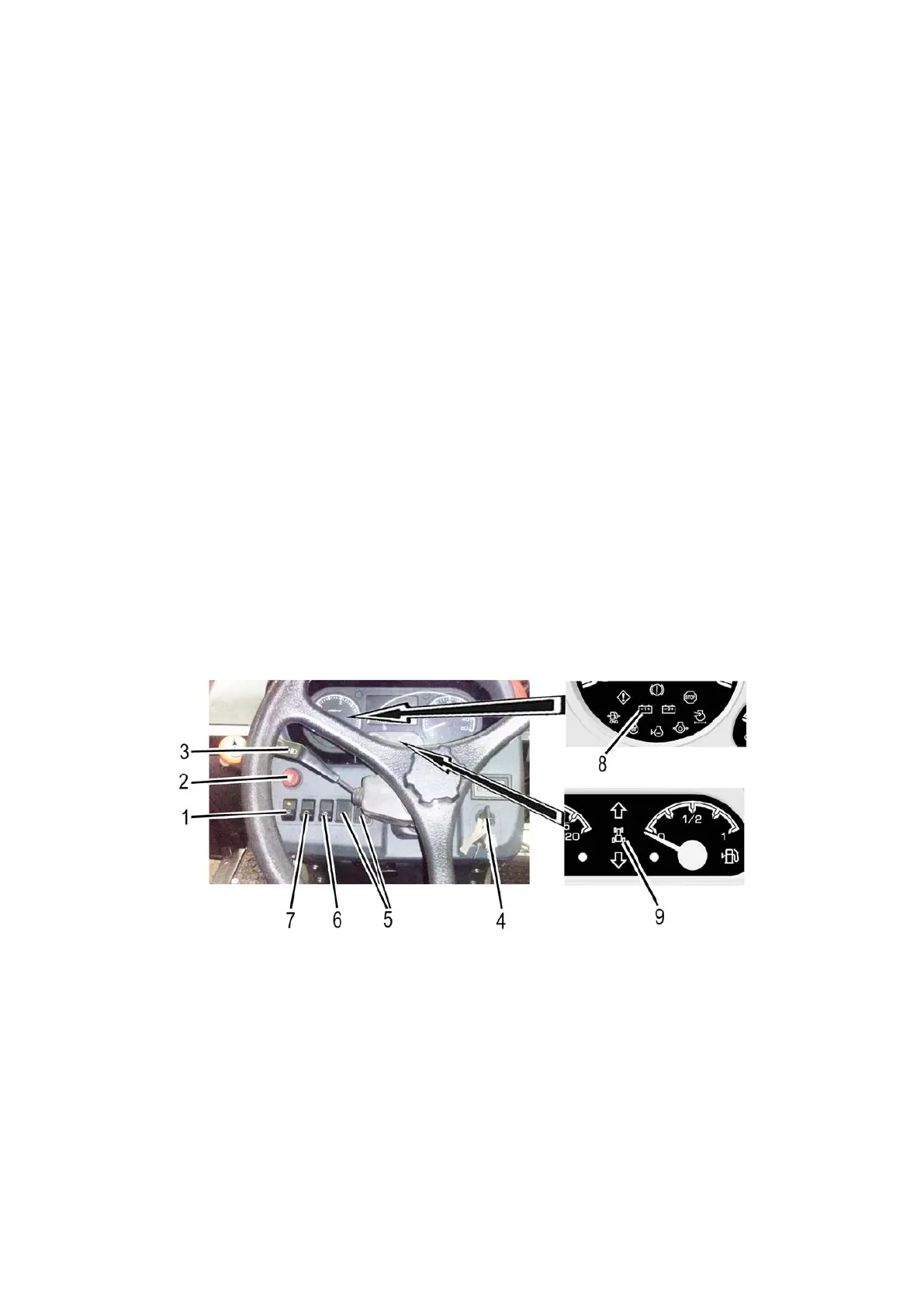
2.2 Switches of dashboard, engine stop handle, battery switch
1 – switch of front working lights, mounted on handrails; 2 – emergency flashing
switch; 3 – multifunctional steering column switch; 4 – starter and instruments switch;
5 – blind plugs; 6 – windscreen washer switch; 7 – central light switch; 8, 9 – battery on/off
annunciator.
Figure 2.2.1 – Switches of instrument board
The starter and instruments switch 4 (see Figure2.2.1) has four positions:
- “0” – off;
- “I” – instruments panel; heating plugs are on;
- “II” – starter is on (non-fixed position);
- “III” – radio set is on.