82.3-0000010 OM
63
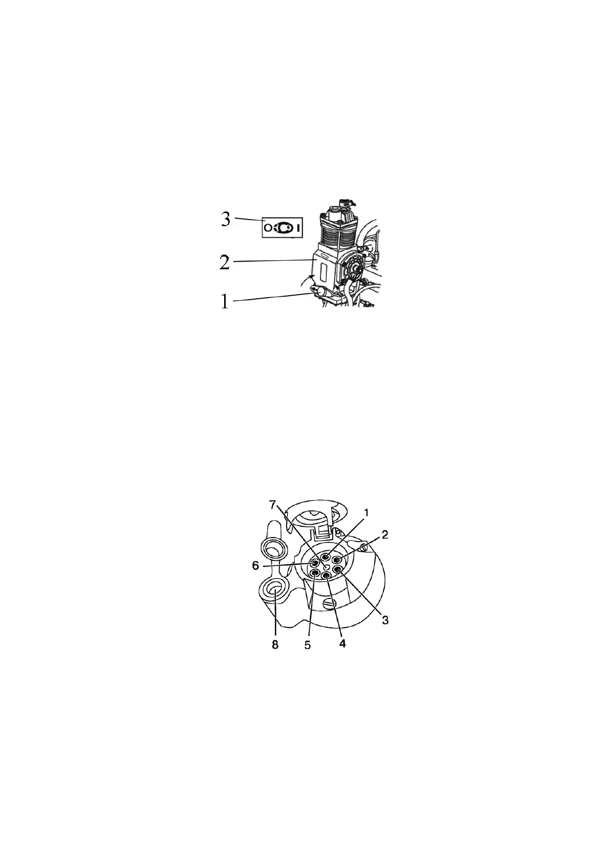
2.20 Control of pneumatic system compressor
Handle to activate the pneumatic system compressor 1 (Figure 2.20.1) has two posi-
tions:
• left (the arrow on the handle is directed forward as viewed along tractor movement)
– “compressor off”,
• right (the arrow on the handle is directed backward, toward tractor cab) – “compres-
sor on”.
ATTENTION: TURN THE PNEUMATIC SYSTEM COMPRESSOR ON AND OFF
ONLY WITH THE ENGINE STOPPED OR WITH MINIMUM IDLE SPEED OF THE EN-
GINE!
1 – handle to turn the pneumatic system compressor on; 2 – pneumatic system
compressor; 3 – diagram of pneumatic system compressor control.
Figure 2.20.1 – Pneumatic system compressor control
Note – The figure 2.20.1 shows position “pneumatic system compressor off”.
2.21 Connector elements of the electrical equipment
2.21.1 Socket to connect electrical equipment of coupled agricultural equipment
A standard seven-pin socket with an additional receiver to connect a portable lamp
(Figure2.22.1) is intended to connect current load of a trailer or trailed agricultural imple-
ment. It is mounted on the rear cab support. A male plug of wire harness from a trailer or
coupled machines is connected to the socket.
1 – left turn indicator; 2 – acoustic signal; 3 – “ground”; 4 – right turn indicator;
5 – right marker lamp; 6 – brake light; 7 – left marker lamp; 8 – receiver to connect a port-
able lamp or other electrical elements with consumed current up to 8A or 12A, depending
on the socket type.
Figure 2.21.1 – Assignment of terminals of seven-pin socket with an additional re-
ceiver to connect a portable lamp.