82.3-0000010 OM
102
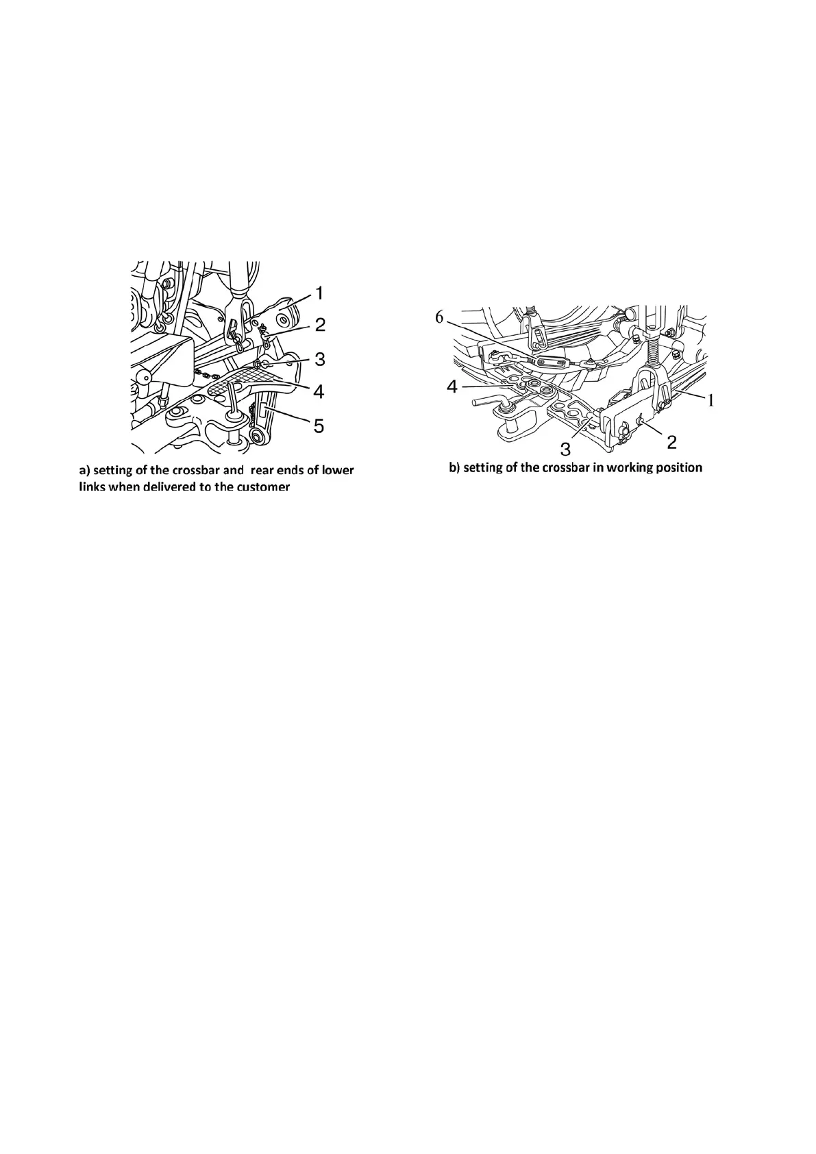
4.3.3.4.2 Setting in working position of crossbar and rear ends of detachable lower links
Tractors “BELARUS-82.3” with detachable lower links are shipped to the customer with
a crossbar and rear ends of lower links, as shown Figure 4.3.11а.
To set the crossbar in working position (as shown in Figure 4.3.11b) perform the follow-
ing operations:
- unlock and remove eye-lugs 3 (Figure 4.3.11), remove crossbar 4;
- unlock and remove pins 2, remove rear ends of lower links 5;
- mount crossbar 4 on the front ends of lower links 1 (as shown of figure 4.3.11b), fas-
ten it by means of eye-lugs 3, pins 2 and cotter pins;
- connect limiting buckles 6 to eye-lugs 3.
1 – front ends of lower links; 2 – pin; 3 – eye-lug; 4 – crossbar; 5 – rear ends of lower links;
6 – limiting buckle.
Figure 4.3.11 – Setting of the crossbar in working position
To install rear ends of lower links 5 (Figure 4.3.11), dismount crossbar 4, and with the help
of eye-lugs 4, pins 2 and cotter pins attach the rear ends of lower links by the front ends of lower
links 1, and attach limiting buckles 6 to eye-lugs 3.
ATTENTION: TRACTORS MAY ONLY BE OPERATED WITH EITHER THE CROSSBAR
INSTALLED OR WITH THE REAR ENDS OF THE LOWER LINKS INSTALLED. DO NOT MOUNT
THE CROSSBAR AND THE REAR ENDS OF THE LOWER LINKS AT THE SAME TIME!
ATTENTION: ON TRACTORS “BELARUS-82.3” MOVEMENT WITH TRAILED MA-
CHINES, ATTACHED TO THE CROSSBAR, AT A SPEED ABOVE 15 KM/H IS FORBIDDEN!
ATTACHMENT OF TRAILERS AND SEMI-TRAILERS TO THE CROSSBAR IS FORBID-
DEN.
When operating the tractor with the use of crossbar, the buckles shall be fully locked in
working position. For that, it is necessary to mount the lower links together with crossbar 4 in hori-
zontal position and to lock the buckles fully in working position, as set forth in subsection 4.3.3.1
“Buckles”.
Note – Basic parameters and characteristics of the crossbar are represented in subsection
4.4 “Tow hitches”.