82.3-0000010 OM
101
When operating agricultural implements, adjust length of the right lifting rod according to
the processing depth.
In order to avoid damage to the RLL units during the transport works and moving, if the
lifting rods are connected to the lower links through grooves B, they must be moved to the
holes A or B of the lifting rods yokes, and the grooves of yokes B must be ahead of the holes if
viewed in the direction of the tractor movement.
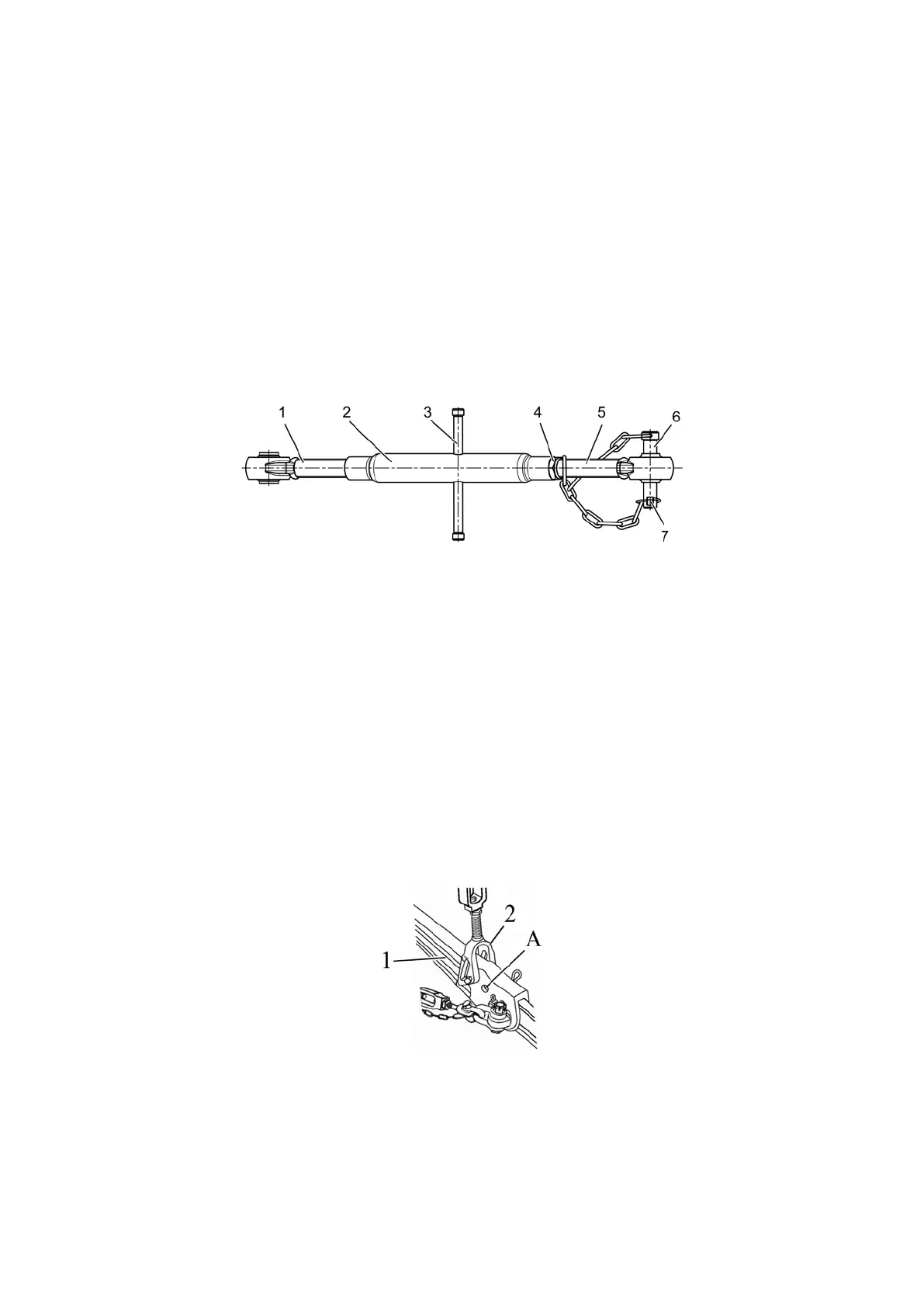
4.3.3.3 Upper link
Upper link is shown in Figure 4.3.9.
The length of the upper link may be adjusted in the range from 500 to 740 mm.
Adjustment of the upper link length shall be made as follows:
- unscrew locknut 4 (Figure 4.3.9);
- by turning handle 3 of pipe 2 clockwise or counterclockwise change the upper link
length;
- having adjusted the link length, lock the screw coupling by locknut 4.
Use pin 6 of rear hinge joint for connection of upper link with the implement, fix the pin
by forelock key with ring 7.
1 – front screw with hinge joint assembly; 2 – pipe; 3 – handle; 4 – locknut, 5 – rear
screw with hinge joint assembly; 6 – pin; 7 – forelock key with ring.
Figure 4.3.9 – Upper link
4.3.3.4 Lower links
4.3.3.4.1 General information
Tractors “BELARUS-82.3” can be equipped with the following types of lower links:
detachable standard with joints, detachable shortened with joints, telescopic with joints or
grips, solid with joints or grips.
On tractors “BELARUS-82.3” additional axes of the lower links are mounted, which
can be used to perform some types of work. When shifting front ends of the lower links
from the main axes on the additional axes of the lower links, it is necessary to readjust the
lengths of the lifting rods and buckles locking in transport and working position.
Mounting of the detachable shortened lower links with a length of 805 mm increases
lifting capacity of the RLL by approx. 10% with reduction of lifting height by approx. 10 %.
An additional point “A” is provided on the front ends of detachable lower links 1
(Figure 4.3.10). When attaching the lifting rod to additional point “A”, the lifting capacity of
the RLL increases by approx. 10%.
1 – front end of the lower link; 2 – lifting rod; А – additional point of lifting rod mounting.
Figure 4.3.10 – Location of the additional point