82.3-0000010 OM
178
5.4.4 Maintenance service every 500 hours of operation (MS-2)
5.4.4.1 General instructions
Perform the previous operations, as well as the operations listed in this subsection
5.4.4.
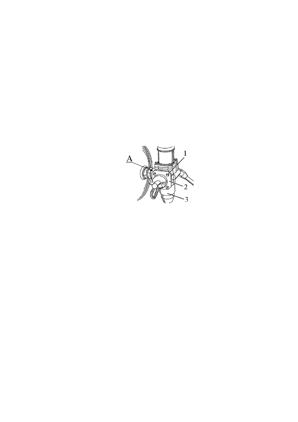
5.4.4.2 Operation 32. Cleaning of filter cartridge of pneumatics air pressure regula-
tor
The operation of cleaning the filter cartridge of the pneumatics air pressure regula-
tor is performed only with the regulator 80-3512010. The designation marking for the air
pressure regulator is located on surface A of the regulator body. On air pressure regulators
of other manufacturers, the filter cartridge cleaning operation is not carried out.
To clean the filter cartridge of air pressure regulator 3 (figure 5.4.34) in the pneu-
matic system, do the following:
- unscrew bolts 1 and remove cover 2;
- remove the filter cartridge, wash it in cleaning solution and blow with compressed
air;
- install the filter cartridge, and then the put cover in place.
1- bolt; 2 – cover; 3 – regulator of air pressure in the pneumatic system.
Figure 5.4.34 – Cleaning the filter cartridge of air pressure regulator
5.4.4.3 Operation 33. Check / adjustment of service brake control
ATTENTION: IT IS REQUIRED TO CHECK AND ADJUST THE BRAKE SYSTEM
AS WELL AS ELIMINATE ANY FAILURES IN IT ONLY WITH THE ENGINE OFF AND
THE TRACTOR PLACED IN HORIZONTAL POSITION AND FIXED BY MEANS OF
CHOCKS UNDER THE WHEELS WHICH EXCLUDE THE TRACTOR SPONTANEOUS
MOVEMENT! ONLY DEALERS ARE ALLOWED TO MAKE ADJUSTMENTS TO THE
BRAKE SYSTEM AND ELIMINATE ANY FAILURES!
When depressed with a force of 120 to 130 N, a full travel of the right brake pedal
shall stay within 105 to 115 mm, and a full travel of the left pedal shall be 5 to 20 mm less
than the full travel of the right pedal under the application of the same force.
If the full travels of the right and the left pedals do not correspond to the specified
values, carry out adjustment of the service brake control.
The service brake control shall be adjusted as follows:
- set pads A (figure 5.4.35) of both pedals in one and the same plane with an accu-
racy of 2 to 3 mm (it is allowed to align the pads by bending legs B);
- undo locknuts 3 (figure 5.4.35) of adjusting bolts 2;
- screw bolts 2 into the yokes or screw them out as much as to make the full travel
of the right pedal stay within 105 to 115 mm under the application of 120 to 130 N force,
while the full travel of the left pedal be 5 to 20 mm less than the right pedal travel to ensure
simultaneous response of the brakes with the pedals interlocked.
- tighten locknuts 3 with a torque of 75 to 95 Nm.