82.3-0000010 OM
177
5.4.3.11 Operation 31. Check/adjustment of clutch pedal free travel
ATTENTION: TOO SUBSTANTIAL PEDAL TRAVEL WILL NOT ALLOW TO DIS-
ENGAGE THE CLUTCH FULLY AND WILL HAMPER GEAR SHIFTING. ABSENCE OF
FREE PEDAL TRAVEL WILL LEAD TO COUPLING DISC SLIPPING, RAPID WEAR OF
THE DISCS AND OVERHEATING OF CLUTCH PARTS!
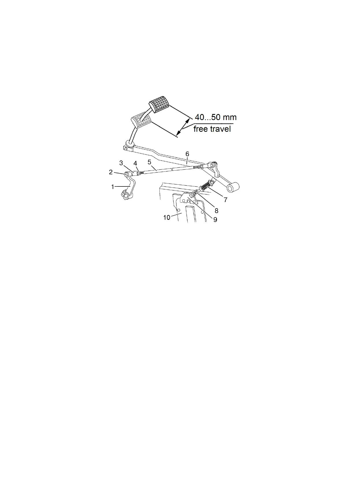
Clutch pedal free travel, measured with non-running engine, shall be within the lim-
its from 40 to 50 mm (as shown in figure 5.4.33). If this value is too high or too low, adjust
clutch pedal free travel.
1 – lever; 2 – pin; 3 – yoke; 4 – lock nut; 5 – link; 6 – pedal; 7 – servo unit; 8 – bolt;
9 – bracket; 10 – cover.
Figure 5.4.33 – Check and adjustment of clutch pedal free travel
To adjust free travel proceed as follows:
- loosen lock nut 4 (figure 5.4.33) of yoke 3, unlock and remove pin 2, disconnect
link 5 from lever 1;
- unscrew adjusting bolt 8 until pedal 6 touches floor of the cabin;
- turn lever 1 anticlockwise against the stop, that is until the release bearing
touches the clutch release levers (on tractors with the coupling clutch of diaphragm type –
until the release bearing touches blades of the diaphragm spring);
- adjust length of ling 5, rotating yoke 3 until holes in the yoke align with the holes
in lever 1. Then screw yoke 3 in by five turns (shorten the link).
- tighten lock nut 4, connect yoke 3 to lever 1 by means of pin 2.
ATTENTION: MAKE SURE THAT THE CLUTCH PEDAL SAFELY RETURNS ALL
THE WAY UNTIL IT STOPS AGAINST THE FLOOR IN THE AREA OF PEDAL FREE
TRAVEL. OTHERWISE, ADJUST FORCE OF THE SPRING OF SERVO UNIT 7 (FIGURE
5.4.33) BY MEANS OF BOLT 8 OR CHANGE THE POSITION OF BRACKET 9, TURN-
ING IT ANTICLOCKWISE RELATIVE TO THE AXIS OF THE MOUNTING BOLT!
 Loading...


