82.3-0000010 OM
31
2.6.4 Liquid crystal display
2.6.4.1 General information
The liquid crystal display 3 (Figure2.6.1) is intended for displaying parameters of
tractor operation and indicating failures of electronic systems in real-time mode.
After finishing the self-testing of needles, annunciators, buzzer and illumination, dur-
ing which a welcome window is shown as presented in Figure 2.6.4, the LCD 3 (Figure
2.6.1) switches to the basic mode of information displaying.
Figure 2.6.4 – Loading mode of the liquid crystal display
2.6.4.2 Basic information display mode
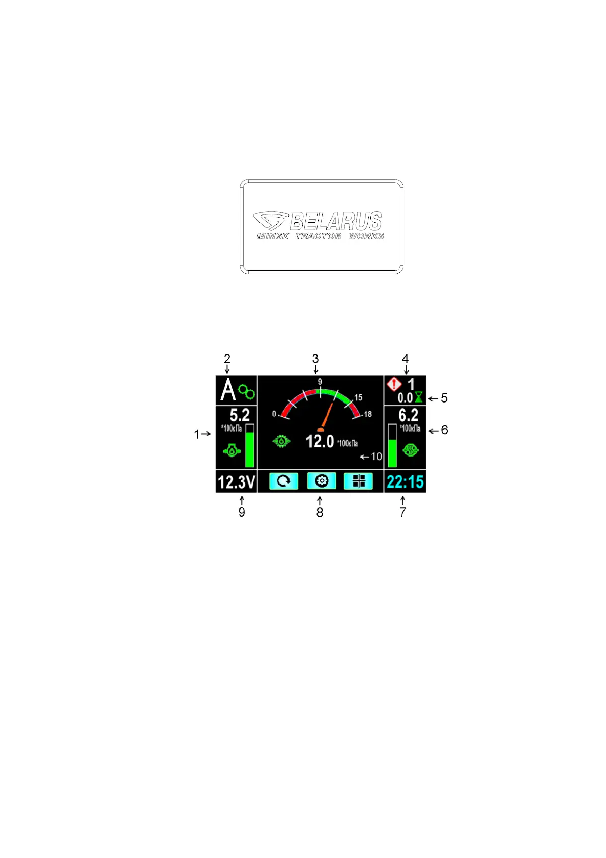
The screen can conventionally be divided into 10 fields. Examples of information
displaying in the basic mode are given in Figure 2.6.5.
1 – Oil pressure in the engine.
2 – Number of engaged gear, transmitted through CAN3 (CECS).
3 – Variable field depending on the screen number.
4 – Total number of non-critical or critical failures.
5 – Tractor running time for a period (h).
6 – Air pressure in the pneumatic system.
7 – Current time.
8 – Hints for control buttons.
9 – Supply voltage.
10 – Field is not in use.
Figure 2.6.5 – Liquid crystal display is basic mode
Note - Figure 2.6.5 shows the operating oil pressure in the transmission in the field
of screen 3.
For display control, the control panel 1 (Figure2.6.6) is provided on the dashboard.
Assignment of buttons 2, 3, 4 is shown on display 3 (Figure2.6.1) and is given in table
2.6.3.