82.3-0000010 OM
27
2.6 Instrument panel
2.6.1 General information
The instrument panel 12 (Figure 2.1.1) includes four needle indicators, as well as
annunciators and a liquid crystal display, as shown in figure 2.6.1.
After turning the starter and instruments switch from position “off” into “instruments
supply”, the instrument panel turns on and performs self-testing of needle indicators, an-
nunciators, buzzer and illumination during a maximum period of 2 seconds. The LCD dis-
plays a welcome window for 2 seconds, as shown in Figure2.6.4.
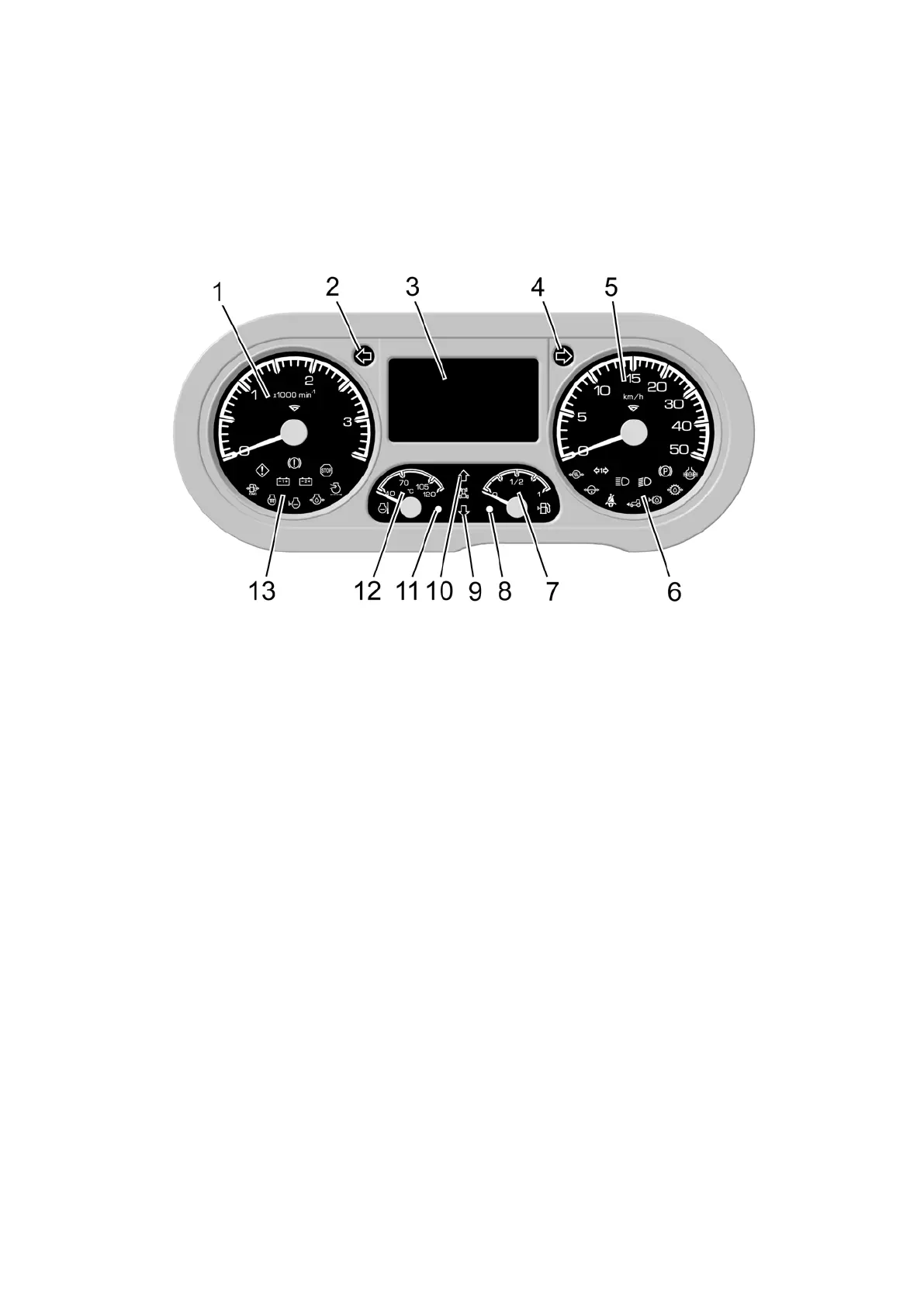
1 – gauge to indicate engine crankshaft speed; 2 – annunciator of tractor left turn
indicators actuation (green); 3 – liquid crystal display; 4 – annunciator of tractor right turn
indicators actuation (green); 5 – travel speed gauge; 6 – annunciators built in travel speed
gauge; 7 – gauge to indicate fuel volume; 8 – annunciator to indicate low fuel volume;
9 – annunciator of reverse gears engagement; 10 – annunciator of forward gears en-
gagement; 11 – annunciator of emergency coolant temperature; 12 – gauge to indicate
coolant temperature; 13 – annunciators built in the crankshaft speed gauge.
Figure 2.6.1 – Instrument panel
2.6.2 Instrument panel indicators
2.6.2.1. Numbers “0”, “1”, “2”, and “3” are marked on the gauge to indicate engine
crankshaft speed 1 (Figure 2.6.1). The division value of the scale equals 100 rpm.
2.6.2.2 Numbers “0”, “5”, “10”, “15”, “20”, “30”, “40” and “50” are marked on the
travel speed gauge 5 (Figure 2.6.1).
The division value of the scale is:
- 1 km/h - in the range from 0 to 20 km/h;
- 2 km/h - in the range from 20 to 50 km/h;
The input signal for travel speed gauge 5 is the signal from rotation frequency pulse
sensors of final drives’ toothed gears of right and left rear wheels. The travel speed gauge
5 readings correspond to the least frequency of input signals coming from the speed sen-
sors of left and right rear wheels. In case one of the signals is missing, the travel speed
values are calculated from the available signal while sending a failure message to the dis-
play 3.