82.3-0000010 OM
49
2.14.4 Control of RLL locking mechanism in transport position on tractors with draft
regulator
Lever 27 of the RLL locking mechanism in transport position (Figure 2.1.1) has two po-
sitions:
"RLL unlocked" – the right most position along the tractor movement;
"RLL locked in upper most (transport) position” – the left most position of the lever.
To lock the RLL in transport position proceed as follows:
- raise the implement to its upper most position, by setting handle 37 (Figure 2.1.1), op-
erating draft control to the position “raising”;
- after setting the RLL to its upper most position, turn the handle 27 (Figure 2.1.1.) to
the left;
- release handle 37 (Figure 2.1.1) operating draft control.
To unlock RLL slightly raise the implement by handle 37 (Figure 2.1.1) that provides
draft control, and turn lever 27 (Figure 2.1.1) to the right.
2.14.5 Control of RLL locking mechanism in transport position on tractors without
draft regulator
Lever 27 of the RLL locking mechanism in transport position (figure 2.1.1) has two posi-
tions:
- “RLL unlocked” – the right most position if viewed in direction of tractor travel;
- “RLL locked in upper (transport) position” – the left most position.
To lock RLL in transport position proceed as follows:
- raise the implement to its upper most position, by setting handle 4 (Figure 2.16.1) of
the HLL distributor to the position “Raising”;
- after you set RLL to its upper most position, turn lever 27 (Figure 2.1.1) to the left;
- release handle 4 (Figure 2.16.1) of the HLL distributor.
To unlock the RLL slightly lift the implement by handle 4 (Figure 2.16.1) and turn lever
27 (figure 2.1.1) to the right.
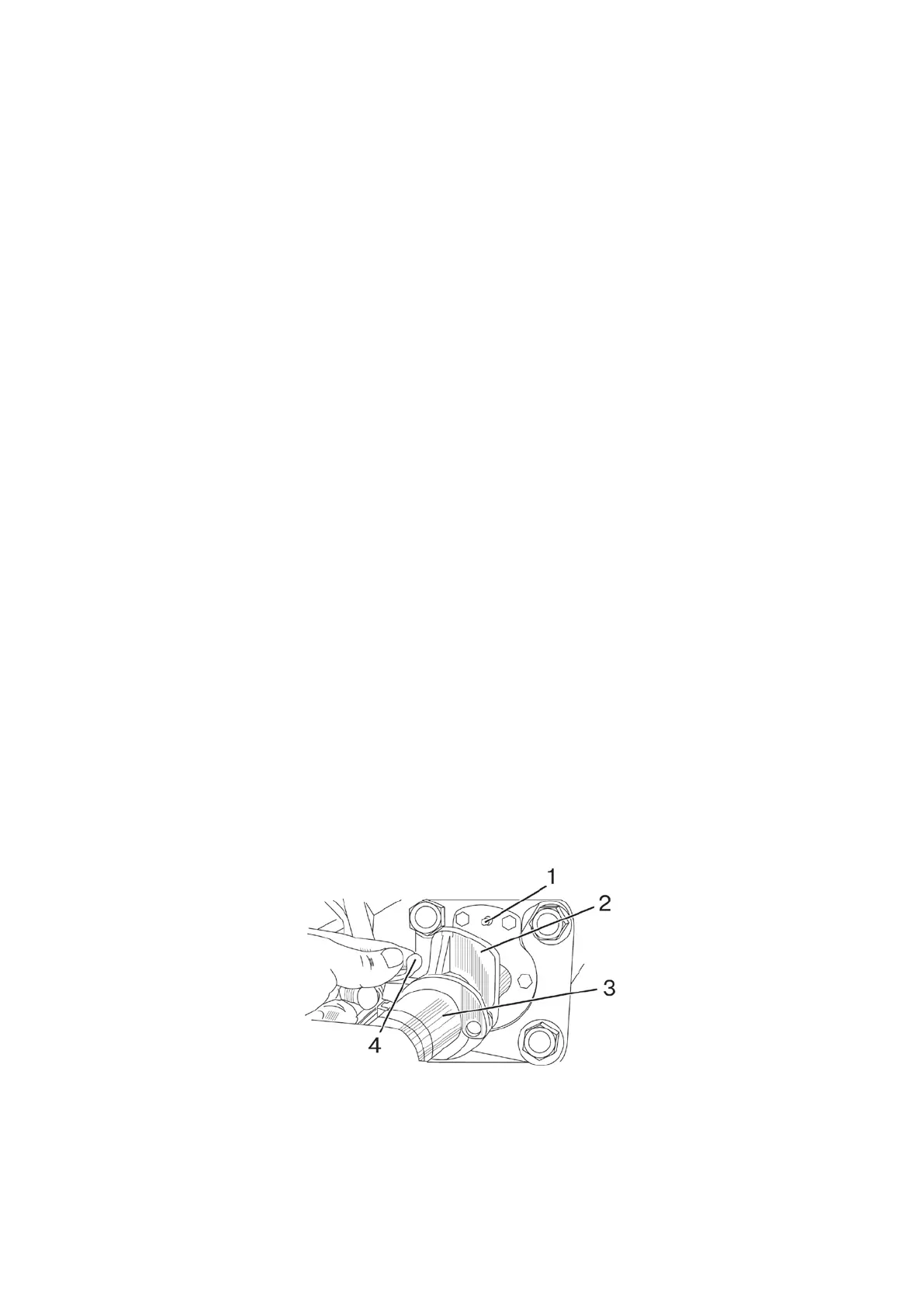
2.14.6 Adjustable implement lift retainer
Adjustable implement lift retainer is mounted on tractors “BELARUS-82.3” upon re-
quest.
Limit the retraction stroke of the rear cylinder rod of the lift linkage mechanism (the
height of the implement raising) with the help adjustable stop 2 (Figure 2.14.3) by performing
the following operations:
- loosen winged nut 4;
- shift adjustable stop 2 along hydraulic cylinder rod 3 to the desired position and tight-
en winged nut 4 by hand. When raising the implement to the desired height, adjustable stop 2
will shift rod 1 of the hydromechanical valve and will block cavities of the cylinder.
1 – rod of the hydromechanical valve; 2 – adjustable stop; 3 – hydraulic cylinder;
4 – winged nut.
Figure 2.14.3 – Adjustable implement lift retainer
ATTENTION: TO AVOID DAMAGE TO THE CABIN BY THE ELEMENTS OF THE
LIFTED IMPLEMENT, ADJUST THE LENGTH OF THE RIGHT AND LEFT CROSSBARS IN
ACCORDANCE WITH THE INSTRUCTIONS IN SUBSECTION 4.3.3.2 “CROSSBAR”!