82.3-0000010 OM
131
At the end of the connecting line, connecting head of valve type 12 is installed. The
valve of the connecting head prevent compressed air outlet, when the pneumatic drive is
used without the trailer (for example, for tire inflation). As the trailer’s brake line is con-
nected to the tractor’s brake line 11, the valve of the connecting head opens, providing
passage of the compressed air from tractor pneumatic drive to the trailer. When intercon-
necting the lines make sure there is no pressure in tank 5 of the tractor.
Air pressure in tank 5 is monitored by air pressure indicator 3 and emergency air
pressure warning lamp 2 of red color (installed on the instrument panel), by air pressure
sensor 4 and emergency air pressure sensor 1, respectively.
To remove condensate from tank 5, a condensate removal valve 6 is provided.
Condensate removal is carried out by deflecting the pusher with a ring to the side and up-
ward.
Bleeding of air from the pneumatic drive (for inflating tires, etc.) is carried out
through air bleed valve 9.
ATTENTION: BEFORE CONNECTING OR DISCONNECTING TRACTOR AND
TRAILER PNEUMATIC LINES, ENGAGE PARKING BRAKE! CONNECT TRACTOR AND
TRAILER PNEUMATIC LINES ONLY WHEN THERE IS NO PRESSURE IN THE PNEU-
MATIC SYSTEM OF THE TRACTOR!
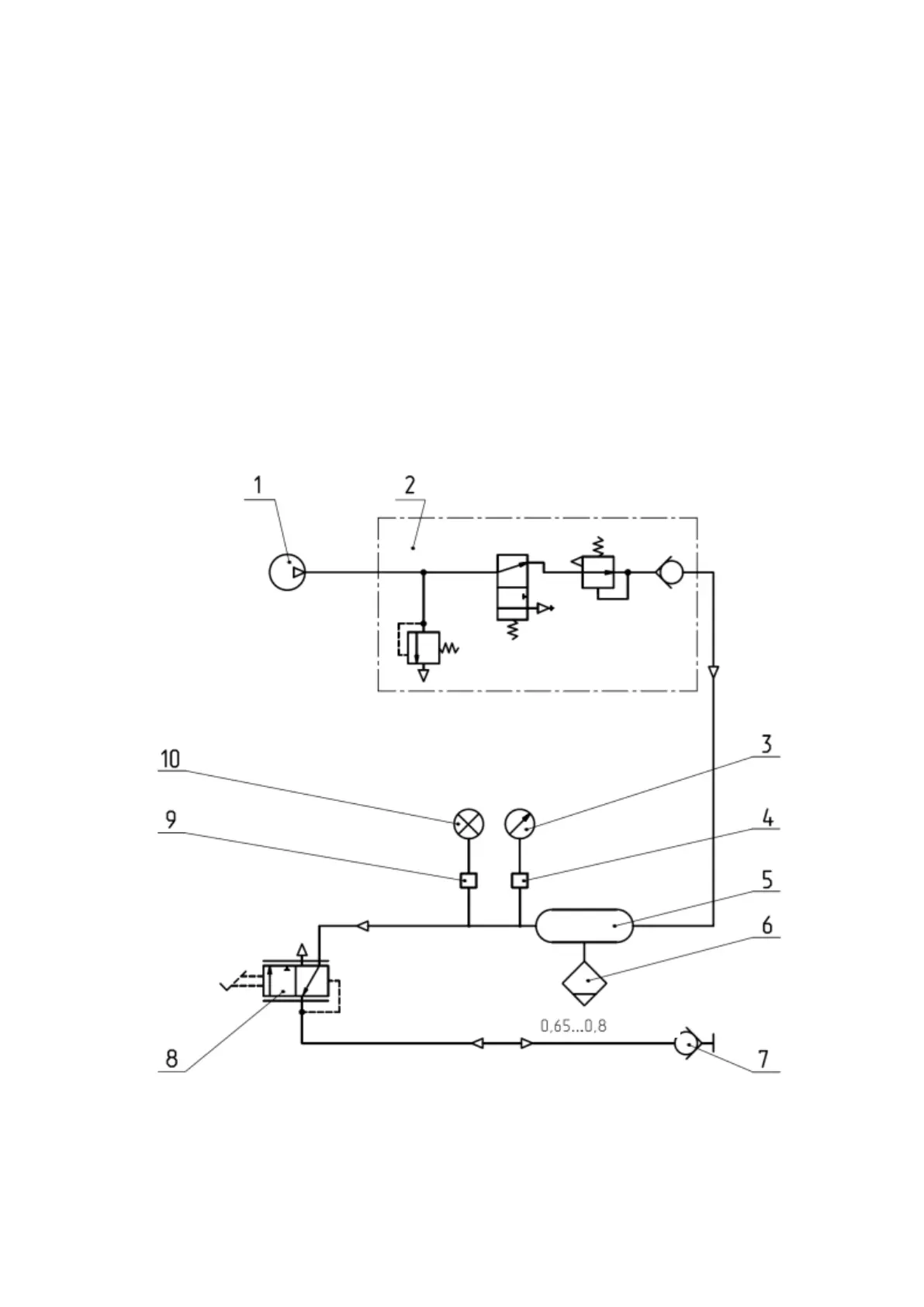
Layout of single-line pneumatic drive is given in figure 4.7.2.
1 – compressor; 2 – pressure regulator; 3 – pressure indicator; 4 – pressure sensor;
5 – tank; 6 – condensate removal valve; 7 – connecting head (black); 8 – brake valve (sin-
gle-line); 9 – emergency pressure sensor; 10 – warning lamp of emergency air pressure.
Figure 4.7.2 – Layout of single-line pneumatic drive