82.3-0000010 OM
148
For installation of the complete set of the loading equipment use the bores on front
beam, frame rails and tractor clutch coupling case. For the purpose of unloading of semi-
frame and tractor clutch coupling case use adjustable bars or other constructive elements
connected to rear semi-axle tubes of the rear axle which transfer a part of push force to
the tractor rear axle. For rigidity maintenance it is desirable, that the right and left parts of
the loader mounting frame are rigidly connected to each other.
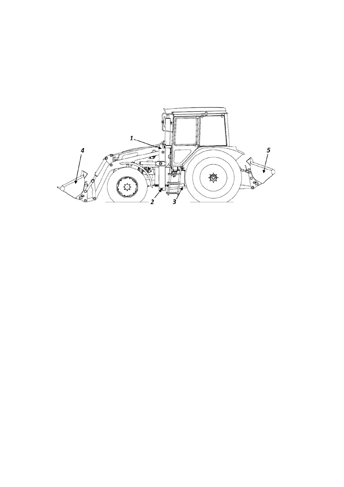
Loader installation scheme is shown in figure 4.13.1.
1 – loading equipment kit for the tractor; 2 – crossed linkage of loader frame;
3 – tapped rod; 4 – loader bucket; 5 – rear ballast weight.
Figure 4.13.1 – Loader installation scheme
To ensure sufficient towing power implemented by tractor rear wheels, it is neces-
sary to create adequate load on the rear axle equal or exceeding 60% of the tractor opera-
tional weight with regard to installed loader weight.
Right proportion of loads on the tractors axles can be achieved by rear axle ballast-
ing by means of loads, solution filled in wheel tires, rear counterweight (suspended bucket
with ballast weight), attached to the rear lift linkage.
ATTENTION: IN LOADER OPERATION MANUAL INTENDED FOR CONSUMER,
LOADER MOUNTING ORDER SHALL BE SET FORTH WITH PICTURES INCLUSIVE OF
DATA ON SHIFTING AND DISMOUNTING OF TRACTOR COMPONENTS.
In a loader design, safety and locking devices (fast coupling clutches, retarder
valves, overload limiters and other), shall be provided for excluding conflicting movement
of mechanisms, overloads and breakages in operation due to excess of admissible pres-
sure values in the hydraulic system, rated load capacity or towing power.
In mode of soil cutting it is necessary to provide protection for the chassis of the
tractor and the loader against overload. One of the options is overturning of the loader
working attachment (bucket, etc.), due to actuation of a special valve integrated in the
loader’s hydraulic system.
In order to avoid breakages, the loader shall be equipped with retarder valves in lift-
ing line of loader hydraulic cylinders, for the purpose of loader lowering speed limitation.
Loader design shall provide possibility of securing working attachments in transport
position.