82.3-0000010 OM
163
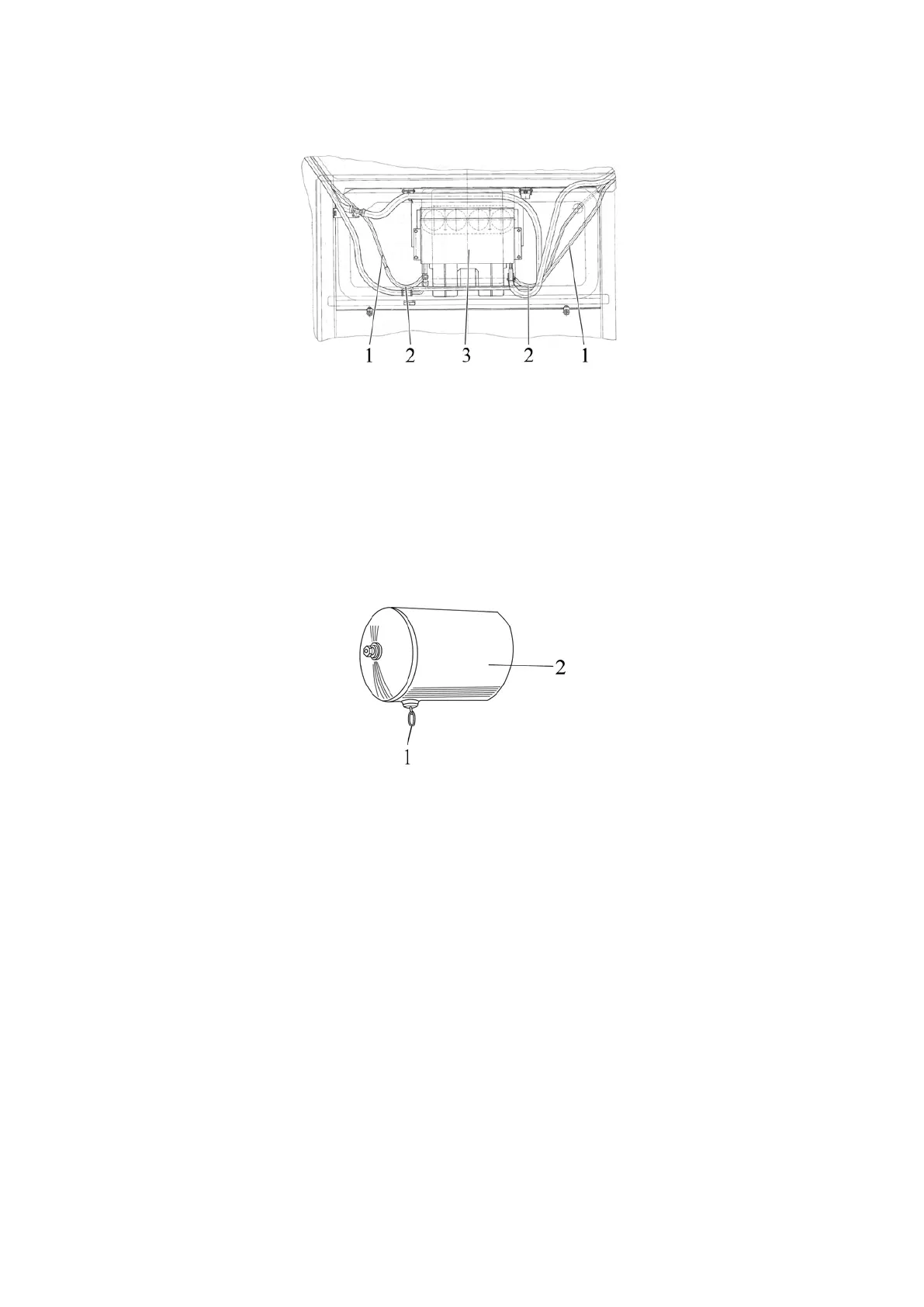
Disconnect drain tubes 1 (figure 5.4.8) from outlets 2 of heater-cooler 3, blow the
tubes with compressed air, reconnect them to outlets 2 of heater-cooler 3.
1 - drainage tube; 2 - outlet of heater-cooler; 3 - heater-cooler.
Figure 5.4.8 - Upper compartment
Reinstall the panel of the cabin upper compartment of the cabin, secure it with two
bolts, mount the caps and the handle of the heater valve.
5.4.1.10 Operation 9. Drainage of condensate from pneumatic system tank
To drain condensate from tank 2 (figure 5.4.9) of the pneumatic system pull drain
valve ring 1, installed on the tank, towards the horizontal direction of any side and hold it
until condensate drains completely.
1 – ring; 2 – pneumatic system tank.
Figure 5.4.9 – Drainage of condensate from pneumatic system tank
5.4.1.11 Operation 10. Check of brakes operability on the move, operability of the
engine, steering, light/alarm devices. Check of condition of electrical cables in the engine
compartment
The following tractor operating parameters shall be ensured:
- the engine shall have stable operation in all modes;
- controls, light warning and acoustic alarm devices shall operate properly;
- simultaneous engagement of the right and left service brake.
In case the abovementioned conditions are not observed adjust as required or re-
pair the respective tractor systems.