82.3-0000010 OM
47
Adjustment speed regulator handwheel 4 is used to adjust the correction speed of
the implements positions during tractor operation. Turning the handwheel 4 clockwise re-
duces the correction speed, turning it counterclockwise increases it. Adjustment of the
handwheel 4 should be carried out after adjustments of the RLL and mounted implements
(plow, cultivator, etc.) have been completed.
When preparing the machine for operation using the draft regulation method, do the
following
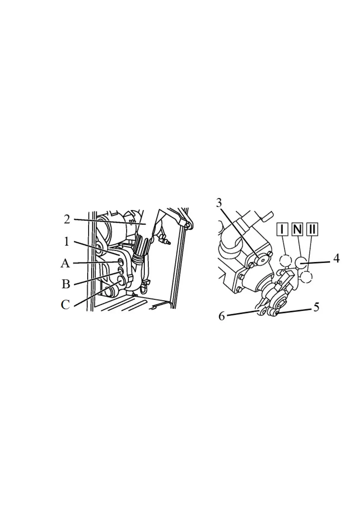
- set the upper link 2 (Figure 2.14.2) of the lift linkage on the upper hole of clevis 1
(position "A" in Figure 2.14.2);
- connect the implement (machine) to the tractor RLL;
- if necessary, make adjustments to the RLL and the implement.
- turn on the draft regulation method. To do this, raise the implement (machine) to
the extreme upper position and insert switch 4 into the slot of the draft lever 5 by turning
the switch to the left (in the direction of tractor travel) to the position "II". For an easier en-
gagement, before putting the switch into the slot, move it forward (in the direction of tractor
travel) until it fits into the slot on lever 5;
- adjust the correction speed regulator handwheel 3. Turning the handwheel clock-
wise reduces the correction speed, turning it counterclockwise increases it. Turn the hand-
wheel to achieve a smooth automatic depth regulation during operation. Do not turn the
handwheel far clockwise against the stop, because it will result in excessively slow raising of
the implement (machine) and will cause increased slipping of the tractor guide wheels.
1 – clevis; 2 – upper link; 3 – correction speed regulator handwheel; 4 – regulation
method switch; 5 – draft lever slot; 6 – position lever slot.
Figure 2.14.2 - Positions of the regulation switch and upper link for draft regulation
At the beginning of the run, lower the mounted implement by turning forward handle 2
(Figure 2.14.1). The further forward the handle, the greater the tillage depth. As you pull han-
dle 2, the depth will decrease. After setting the desired depth, move the limiter 1 along the slot
in the panel until it stops into the handle and fix it.
At the end of the run, to shallow up the implement, set lever 2 to the "raising" position -
pull it against the stop. After the end of the lift, the lever should automatically return to neutral
position "N".
At the beginning of each subsequent run, lower the implement by moving the handle 2
forward against the stop into the limiter 1.
When working in tilling, in cases the obtained depth is still insufficient when pushing the
power regulator handle to the maximum depth, move upper link 2 of the implement to the mid-
dle hole of clevis 1 (position "B" in Figure 2.14.2).
Adjustment of the correction speed handwheel and selection of the hole in the clevis
when installing the upper links must be carried out for specific soil conditions and for each type
of agricultural machine. No readjustments are required during operation.