82.3-0000010 OM
97
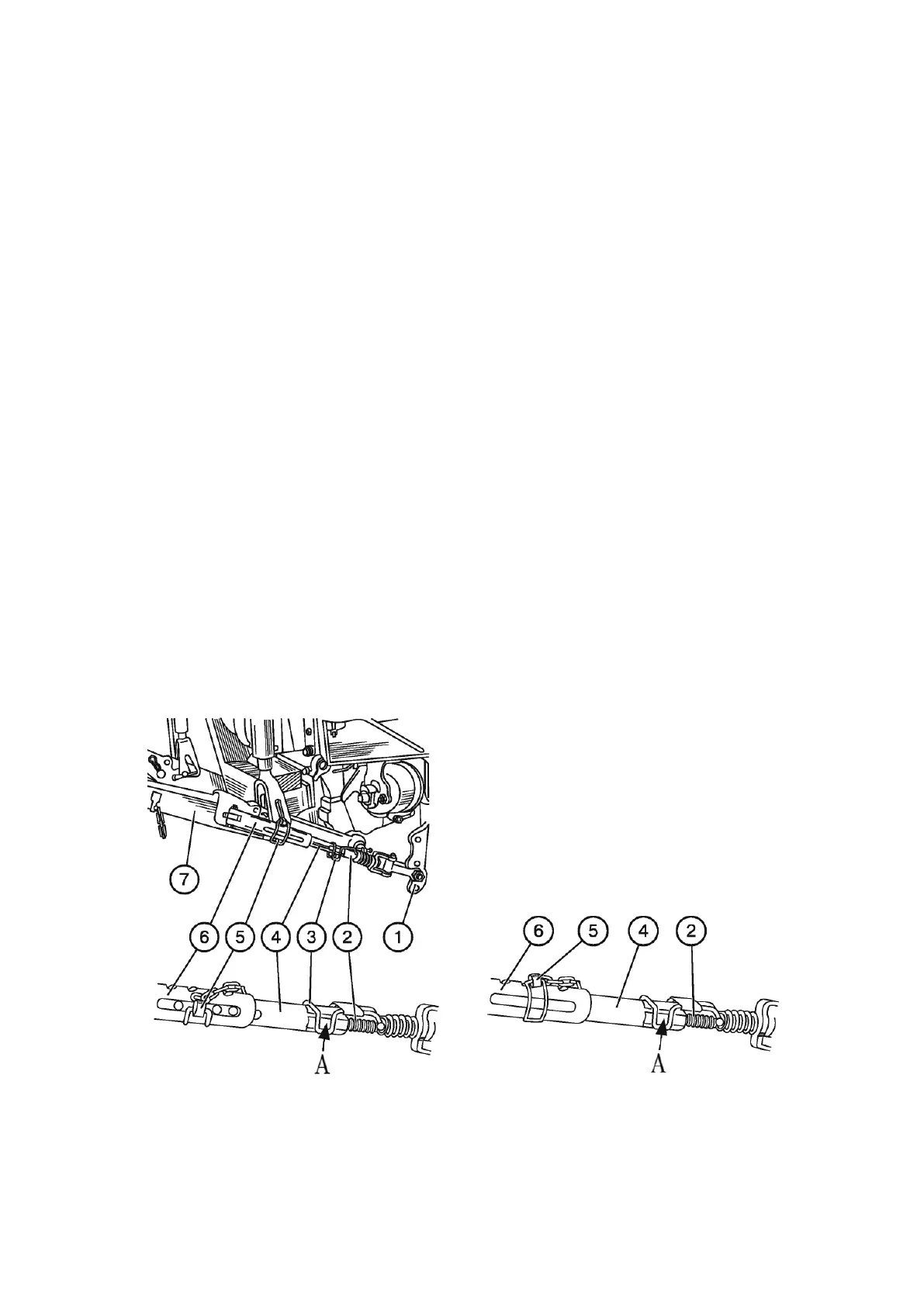
Partial blocking of buckles in operating position shall be made in the following way:
- by turning screw 2 (Figure 4.3.4), set handle 3 in the middle of flattened surface “А”;
- remove forelock key 5 from the buckle;
- attach the machine (implement) to the lower links 7 and lift it a little bit until it takes
off from the ground;
- set the machine (implement) symmetrically to the tractor longitudinal axis;
- match the bores of the inner pipe 4 with a groove in the outer pipe 6, insert fore-
lock key 5 into bore that is closest to the middle of the groove of the inner pipe 4;
- adjust forelock key 5 position by turning screw 2 with handle 3 so that the forelock
key comes to the middle of the groove in the outer pipe 6.
ATTENTION: MOUNT FORELOCK KEY 5 (FIGURE 4.3.4) IN SUCH WAY AS IT IS
POSITIONED IN THE MIDDLE OF THE GROOVE OR WITH MINIMUM DISPLACEMENT
TOWARDS THE TRACTOR. OTHERWISE, BUCKLES CAN BE DAMAGED!
During certain types of operations, lower links of the lift linkage shall be completely
blocked against cross-travel to avoid damages of plants by swinging implement. To this
end, full blocking of buckles in operating position is necessary.
Full blocking of buckles in operating position shall be made as follows:
- by turning screw 2 (Figure 4.3.4), set handle 3 in the middle of flattened surface “А”;
- remove forelock key 5 from the buckle;
- attach the machine (implement) to the lower links 7 and lift it a little bit until it takes
off from the ground;
- set the machine (implement) symmetrically to the tractor longitudinal axis;
- turn inner pipe 4 by hand to place its bores in the upper part of the pipe;
- match one of the bores in the inner pipe 4 with the nearest hole in the outer pipe 6
and insert forelock key 5 into them;
- check side-sway range of the machine (implement), it shall not exceed 20 mm to
each side;
- adjust side-sway range of the machine (implement), if necessary, by turning screw 2.
а) Partial blocking of telescopic buckles b) Full blocking of telescopic buckles
1 – bracket; 2 – screw; 3 – handle; 4 – inner pipe; 5 – forelock key; 6 – outer pipe;
7 – lower link.
Figure 4.3.4 – Partial and full blocking of telescopic buckles